

Young explorers welcome to the fascinating world of Arduino and motor control! Today, we began an exciting attempt to discover the L298N Motor Drive’s mysteries. we demonstrate how this tiny module enables you to control motors with your Arduino, get ready to see the wonder of electronics in action. Get ready to explore the endless possibilities of robotics and let your creativity run wild!

1. What is the L298N Motor Drive?
The speed and direction of motors can be controlled by using the integrated circuit (IC) L298N Motor Drive, which is frequently used in robotics and automation projects.
It provides a link between the motors and the microcontroller, such as Arduino, allowing accurate movement control.
no only arduino.we can use L298N Motor Drive in various platforms like Raspberry Pi, ESP32, STM32, or BeagleBone.
2. Features of L298N Motor Drive
The L298N Motor Drive can drive up to two DC motors or one bipolar stepper motor.

DC motors

bipolar stepper motor
It provides a maximum current output of 2A per channel and accepts a wide range of input voltages (5V to 46V).
It guards against circuitry damage given on by reverse current from the motor because of its built-in protection diodes.
3. Making Connections
To get started, use jumper wires to connect the L298N Motor Drive to your Arduino board.

read more about jumpers and other components…
Make sure the L298N is properly connected to the power source (battery or adapter).
Make sure to match the polarity when connecting the motor(s) to the L298N’s motor output terminals.
4. Control Pins and Logic

The direction of the left-hand side motor is controlled by the IN1 and IN2 pins, whereas the direction of the right-hand side motor is controlled by the IN3 and IN4 pins.
ENA and ENB pins control the speed of each left and right-hand side motor.
In VCC, you need to supply power (+) and in Ground, you need to supply ground voltage(-). Ensure that the ground pin on your Arduino is also connected to this one.
The L298N’s 5V pin is made to offer a regulated 5V output to power external devices like sensors or microcontrollers that need a 5V supply.
Attach the wires to ENA and ENB pins if you want to control each motor. otherwise, you don’t need to consider those pins. motors run at idle speed.
Before attaching the jumpers, be sure to remove the clips in ENA and ENB.

You can make the motors move forward, backwards, or stop by adjusting these pins using Arduino code.
5. PWM and Speed Control
let’s consider specifically PWM signals.
Pulse width modulation, or PWM, is a technique for encoding data in digital signals that involves changing the width or duration of the signal’s high and low states.
Pulse Width Modulation (PWM) is supported by the L298N Motor Drive, allowing you to regulate the motors’ speed.
The motor speed can be varied in your Arduino code to produce smooth and precise movements.
6. Let’s Code!
if you want to learn the basics then visit this…
1. Gather the Required Components
- L298N Motor Drive module
- Two DC motors
- Arduino Uno board
- Breadboard and jumper wires
- External power supply (6V – 12V)
2. Connect the L298N Motor Drive
- The L298N Motor Drive module should be placed on the breadboard.
- Connect the Arduino Uno board’s 5V pin to the L298N’s VMS pin.
- Connect the Arduino Uno board’s GND pin to the GND pin on the L298N.
- Connect the Arduino Uno board’s digital pin 9 to the L298N’s ENA pin.
- Connect the Arduino Uno board’s digital pin 10 to the L298N’s ENB pin.
- Connect the Arduino Uno board’s digital pins 8, 7, 6, and 5 to the L298N’s IN1, IN2, IN3, and IN4 pins, respectively.
- Connect one of the DC motors to the L298N’s OUT1 and OUT2 pins.(left-hand side )
- The other DC motor should be connected to the L298N’s OUT3 and OUT4 pins. (right-hand side)
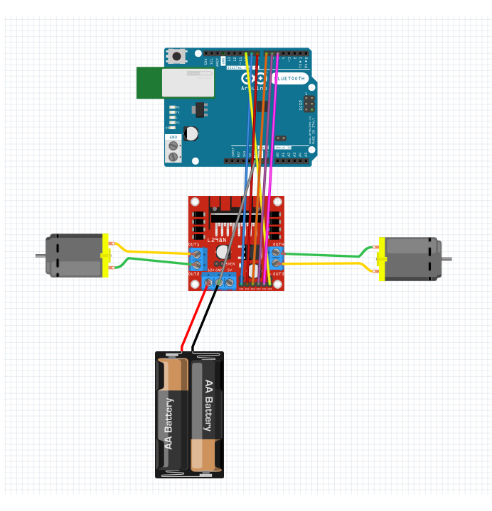
3. Power Up the Circuit:
Connect the positive terminal of the external power supply to the L298N’s +12V pin.
Connect the L298N’s GND pin to the negative terminal of the external power supply.
4. Upload the Arduino Code
int motorPin1 = 8; // Pin connected to IN1 on L298N
int motorPin2 = 7; // Pin connected to IN2 on L298N
int motorPin3 = 6; // Pin connected to IN3 on L298N
int motorPin4 = 5; // Pin connected to IN4 on L298N
int motorPinENA = 9; // Pin connected to ENA on L298N
int motorPinENB = 10; // Pin connected to ENB on L298N


void setup() {
  pinMode(motorPin1, OUTPUT);
  pinMode(motorPin2, OUTPUT);
  pinMode(motorPin3, OUTPUT);
  pinMode(motorPin4, OUTPUT);
pinMode(motorPinENA, OUTPUT);
pinMode(motorPinENB, OUTPUT);
}

void loop() {
  // Run both motors forward
  digitalWrite(motorPin1, HIGH);
  digitalWrite(motorPin2, LOW);
  digitalWrite(motorPin3, HIGH);
  digitalWrite(motorPin4, LOW);

  // Delay for a few seconds
  delay(3000);

  // Stop both motors
  digitalWrite(motorPin1, LOW);
  digitalWrite(motorPin2, LOW);
  digitalWrite(motorPin3, LOW);
  digitalWrite(motorPin4, LOW);

  // Delay for a few seconds
  delay(2000);

  // Run both motors backward
  digitalWrite(motorPin1, LOW);
  digitalWrite(motorPin2, HIGH);
  digitalWrite(motorPin3, LOW);
  digitalWrite(motorPin4, HIGH);

  // Delay for a few seconds
  delay(3000);

  // Stop both motors
  digitalWrite(motorPin1, LOW);
  digitalWrite(motorPin2, LOW);
  digitalWrite(motorPin3, LOW);
  digitalWrite(motorPin4, LOW);

  // Delay for a few seconds
  delay(2000);

  //Same thing with low speed

// Run both motors forward
  analogWrite(motorPinENA,128);//code for pwm pin
  analogWrite(motorPinENB,128);//code for pwm pin
  digitalWrite(motorPin1, HIGH);
  digitalWrite(motorPin2, LOW);
  digitalWrite(motorPin3, HIGH);
  digitalWrite(motorPin4, LOW);

  // Delay for a few seconds
  delay(3000);

  // Stop both motors
  digitalWrite(motorPin1, LOW);
  digitalWrite(motorPin2, LOW);
  digitalWrite(motorPin3, LOW);
  digitalWrite(motorPin4, LOW);

  // Delay for a few seconds
  delay(2000);

  // Run both motors backward
  digitalWrite(motorPin1, LOW);
  digitalWrite(motorPin2, HIGH);
  digitalWrite(motorPin3, LOW);
  digitalWrite(motorPin4, HIGH);

  // Delay for a few seconds
  delay(3000);

  // Stop both motors
  digitalWrite(motorPin1, LOW);
  digitalWrite(motorPin2, LOW);
  digitalWrite(motorPin3, LOW);
  digitalWrite(motorPin4, LOW);
}
congratulations! You currently understand how to use the L298N Motor Drive to operate two DC motors. Your robotic fantasies can now come true thanks to you! Continue learning about embedded systems and electronics, and be as creative as you like! The future is up to you to create!
follow our Arduino section.