

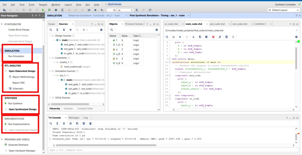
VHDL serves as a hardware programming language utilized in conjunction with Vivado, which acts as our primary development environment. Within Vivado, we have access to simulation, analysis, and testing tools that facilitate the thorough evaluation of our VHDL code before deploying it to our FPGA.
VHDL, or Very High-Speed Integrated Circuit Hardware Description Language, is a hardware description language primarily used for modelling and designing digital electronic systems. Another prominent command language in this domain is Verilog.
Read the beginning of the FPGA
In this article, we concentrate solely on VHDL code and explain the topic using just 5 simple steps.

1. Coding Architecture of VHDL
The overall structure, design, and organization of a software application or system are typically referred to as the “coding architecture” in the context of programming languages. We have 9 coding architectures, such as Microservices Architecture, Object-Oriented Programming, MVC (Model-View-Controller), Service-Oriented Architecture (SOA), Domain-Driven Design (DDD), and more.
When considering Python or Arduino, both languages can be utilized following various architectures such as MVC, MVVM, OOP, and more.
Also, remember that VHDL is not a case-sensitive language.
Basically, VHDL has 2 sections (Entities, Architectures)
Entities
In the beginning of VHDL code, the entity defines the inputs, outputs, and variables required, along with libraries such as IEEE and IEEE.STD_LOGIC_1164.
entity entity_name is
  port (
    -- List of input and output ports
    input_port1 : in data_type1;
    output_port1 : out data_type2;
    -- Additional ports if needed
  );
end entity_name;
We can assign a new name to ‘entity_name’. The comment lines are denoted by ‘— List of input and output ports’, and ‘— Additional ports if needed’.
In ‘input_port1’ and ‘output_port1’, we can assign variable names ‘in’ and ‘out’, respectively, as the default syntax. Finally, for ‘data_type1’ and ‘data_type2′, we need to specify the data types of the variables.
Additionally, it is essential to consider the data types of the inputs and outputs.
Data Types
In VHDL coding, there are 3 main working data types.
Enumerated Types :
Enumerated types are helpful when you have a definite, well-defined set of alternatives or choices for a variable and you want to use descriptive names rather than numeric values to make the code more legible and maintainable.
Built-in Enumerated Types are
The most fundamental type of digital logic is represented by the data type STD_LOGIC. In hardware designs, it is employed to simulate and model digital signals. which contains specified values that correspond to various logic states.
- ‘U’ stands for uninitialized
- ‘X’ stands for unknown
- ‘0’ stands for low
- ‘1’ stands for high
- ‘Z’ stands for high impedance
- ‘W’ stands for weak unknown
- ‘L’ stands for weak low
- ‘H’ stands for weak high
- ‘-‘ stands for don’t care
Bit Vector Types
In VHDL, two types of Bit Vector data are commonly used.
A data type called BIT_VECTOR represents an array of distinct bits. Another data type in VHDL called STD_LOGIC_VECTOR represents an array of digital signals using the STD_LOGIC type.
Integer Type: INTEGER
The built-in data type INTEGER is used to represent signed integer numbers. Within a given range, it can store full numbers in both positive and negative directions. The INTEGER type’s range varies depending on the implementation but is normally between -2,147,483,648 and 2,147,483,647.
Read more about VHDL data types
Architectures
A digital circuit or module’s internal structure and behaviour are defined by the relevant entity’s specification of the architecture in VHDL. The internal processing and connections between the entity’s inputs and outputs are described.
architecture architecture_name of entity_name is
  -- Internal signal declarations (optional)
  signal internal_signal : data_type3;
begin
  -- Description of the internal behavior using concurrent statements, processes, etc.
  -- This is where the actual logic of the entity is defined.

  -- Concurrent statements or process blocks go here.
  -- They specify the behavior of the architecture.

end architecture_name;
Real example of Architecture
architecture behav1 of AND_ent is
begin

    process(x, y)
    begin
        -- compare to truth table
        if ((x='1') and (y='1')) then  -- Key line: Logical AND operation implementation
	    F <= '1';                 -- Key line: Output 'F' set to '1' when both 'x' and 'y' are '1'
	else
	    F <= '0';                 -- Key line: Output 'F' set to '0' for all other cases
	end if;
    end process;

end behav1;

architecture behav2 of AND_ent is
begin

    F <= x and y;                   -- Key line: Simple assignment using the AND operator

end behav2;
In VHDL coding, we employ three types of Architecture modelling: Behavioral, Data Flow, and Structural.
- Behavioural Modeling: Behavioral Modeling is a simple way of writing VHDL code where we only focus on defining the input values and the desired output without delving into the internal behaviours of the components
- Data Flow Modeling: Data Flow Modeling is a more advanced approach where we explicitly specify the logic gates and logical operations (such as AND, OR, XOR, etc.) within the code.
- Structural Modeling: Structural Modeling consists of two subsections: The declaration part and the Statement part. In this approach, we first declare our sub-logic parts separately, and then we import those parts into the main code. we use more than one file in this modelling.
Also, finally, we have the option to use a combination of the above modelling types, known as Mixed Modeling.
Behavioural modelling and data flow modelling are similar in some aspects.
Behavioural Modelling
Sample “AND” gate code
-- Entity declaration
entity AND_gate is
  port (
    input_a : in std_logic;
    input_b : in std_logic;
    output_result : out std_logic
  );
end AND_gate;

-- Architecture definition
architecture behavioral of AND_gate is
begin
  -- Behavioral description using Boolean equation
  output_result <= input_a and input_b;
end behavioral;
Data Flow Modelling
Sample “AND” gate code
-- Entity declaration
entity AND_gate is
  port (
    input_a : in std_logic;
    input_b : in std_logic;
    output_result : out std_logic
  );
end AND_gate;

-- Architecture definition
architecture dataflow of AND_gate is
begin
  -- Data Flow Modeling using concurrent signal assignment
  output_result <= input_a and input_b;
end dataflow;
Structural Modelling
sample custom logic model
F= a*b+a*not(b)
- Create the
and_gate.vhdlfile for the AND gate:
library IEEE;
use IEEE.STD_LOGIC_1164.ALL;

entity and_gate is
  port (
    input_a : in std_logic;
    input_b : in std_logic;
    output_result : out std_logic
  );
end entity and_gate;

architecture behavioral of and_gate is
begin
  output_result <= input_a and input_b;
end architecture behavioral;
2. Create the or_gate.vhdl file for the OR gate:
library IEEE;
use IEEE.STD_LOGIC_1164.ALL;

entity or_gate is
  port (
    input_a : in std_logic;
    input_b : in std_logic;
    output_result : out std_logic
  );
end entity or_gate;

architecture behavioral of or_gate is
begin
  output_result <= input_a or input_b;
end architecture behavioral;
3. Create the not_gate.vhdl file for the NOT gate:
library IEEE;
use IEEE.STD_LOGIC_1164.ALL;

entity not_gate is
  port (
    input_a : in std_logic;
    output_result : out std_logic
  );
end entity not_gate;

architecture behavioral of not_gate is
begin
  output_result <= not input_a;
end architecture behavioral;
Now, create the main file main.vhdl and instantiate the AND and OR gates:
library IEEE;
use IEEE.STD_LOGIC_1164.ALL;

entity main is
  port (
    a : in std_logic;
    b : in std_logic;
    F : out std_logic
  );
end entity main;

architecture structural of main is
  -- Declare the signals to store intermediate results
  signal intermediate_1, intermediate_2 : std_logic;

  -- Component declarations
  component and_gate
    port (
      input_a : in std_logic;
      input_b : in std_logic;
      output_result : out std_logic
    );
  end component;

  component or_gate
    port (
      input_a : in std_logic;
      input_b : in std_logic;
      output_result : out std_logic
    );
  end component;

  component not_gate
    port (
      input_a : in std_logic;
      output_result : out std_logic
    );
  end component;

begin
  -- Instantiate AND gate
  and_gate_1 : and_gate
    port map (
      input_a => a,
      input_b => b,
      output_result => intermediate_1
    );

  -- Instantiate NOT gate
  not_gate_1 : not_gate
    port map (
      input_a => b,
      output_result => intermediate_2
    );

  -- Instantiate OR gate
  or_gate_1 : or_gate
    port map (
      input_a => intermediate_1,
      input_b => intermediate_2,
      output_result => F
    );
end architecture structural;
Example for VHDL coding architecture.
--------------------------------------------------
-- AND gate (ESD book figure 2.3)
-- two descriptions provided
-- More details at: https://circuitprofessor.com/
--------------------------------------------------

library ieee;
use ieee.std_logic_1164.all;

--------------------------------------------------

entity AND_ent is
port(	x: in std_logic;
	y: in std_logic;
	F: out std_logic
);
end AND_ent;

--------------------------------------------------

architecture behav1 of AND_ent is
begin

    process(x, y)
    begin
        -- compare to truth table
        if ((x='1') and (y='1')) then
	    F <= '1';
	else
	    F <= '0';
	end if;
    end process;

end behav1;

architecture behav2 of AND_ent is
begin

    F <= x and y;

end behav2;

--------------------------------------------------
2. Syntax
Environment
We have seven VHDL programming environments, namely Xilinx Vivado, Altera Quartus Prime, ModelSim, GHDL, Sigasi Studio, ISE Design Suite (Obsolete), and Lattice Diamond.
Xilinx Vivado is a more popular environment in VHDL programming.
Click here to learn about creating a simple project in Vivado.
Inside the Vivado environment, we typically perform 8 tasks.(Design Entry,Simulation, Synthesis,Implementation, Bitstream Generation, Configuration and Programming, Verification and Debugging, Documentation)
Operators
Basically, we use 8 operators(and,or,xor,not,nand,nor,xnor,logic shift) in VHDL programming
1.’and’
The AND operator combines two operands in a bitwise manner.
result <= operand1 and operand2;
2.’or’
The bitwise OR operation between two operands is carried out by the OR operator.
result <= operand1 or operand2;
3.’not’
A single bit is bitwise negated or inverted by the NOT operator.
result <= not operand;
4.’nand’
The bitwise AND operation is followed by a negation when using the NAND operator.
result <= not (operand1 and operand2);
5.’nor’
The bitwise OR operation is carried out by the NOR operator, then the result is negated.
result <= not (operand1 or operand2);
6.’xor’
The bitwise exclusive OR operation between two operands is carried out by the XOR operator.
result <= operand1 xor operand2;
7.’xnor’
A bitwise exclusive NOR operation is carried out between two operands using the XNOR operator.
result <= not (operand1 xor operand2);
8.’Logical Shift’
In order to move bits left or right, VHDL includes logical shift operators.
Left Shift (SLL) Operator:
result <= operand sll shift_amount;
Right Shift (SRL) Operator:
result <= operand srl shift_amount;
Variable define
variable variable_name : data_type;
“Variable is a keyword in the VHDL language, and when using it, you should replace ‘variable_name’ with the desired name for your variable, and ‘data_type’ with the appropriate data type, such as std_logic, integer, or boolean. These are the most commonly used data types in VHDL programming.”
also we can use vector types variables
variable signal_vector : std_logic_vector(7 downto 0);
variable data_bus : std_logic_vector(31 to 0);
There are two types of variables defined in VHDL code: one in Port Definition in Entity and another one in Variable Definition in Architecture.
Port Definition in Entity
entity Example_Entity is
  port (
    input_signal : in std_logic;
    output_signal : out std_logic
  );
end entity Example_Entity;
Variable Definition in Architecture
variable temp_variable : std_logic;
variable counter_val : integer := 0;
This is a full sample code where you can identify the differences:
library ieee;
use ieee.std_logic_1164.all;

--------------------------------------------------

entity AND_ent is
port(	x: in std_logic;
	y: in std_logic;
	F: out std_logic
);
end AND_ent;

--------------------------------------------------

architecture behav1 of AND_ent is
begin

    process(x, y)
    begin
        -- compare to truth table
        if ((x='1') and (y='1')) then
	    F <= '1';
	else
	    F <= '0';
	end if;
    end process;

end behav1;

architecture behav2 of AND_ent is
begin

    F <= x and y;

end behav2;
3. libraries
“IEEE” is the main library used in VHDL programming. It provides the “std_logic_1164” package for defining the “std_logic” type and offering common logical operators and other utilities. Additionally, it includes the “numeric_std” and “numeric_bit” packages for performing arithmetic operations on “std_logic_vector” and “unsigned” data types.
library ieee;
use ieee.std_logic_1164.all;
We can use paid libraries for specific tasks like (pg2, Synopsys DesignWare IP, Microsemi Libero IP, Lattice Diamond Standard IP, Xilinx LogiCORE IP). Most of them are IPs, which stand for “Intellectual Properties,” representing pre-designed and pre-verified modules or components intended for reuse in larger digital designs.
4. Examples
And gate
-- This is an AND gate example.
-- You can learn more at: https://circuitprofessor.com/

library ieee;
use ieee.std_logic_1164.all;

--------------------------------------------------

entity Custom_AND_Gate is
  port (
    input1 : in std_logic;
    input2 : in std_logic;
    output : out std_logic
  );
end entity Custom_AND_Gate;

--------------------------------------------------

architecture Behavioral1 of Custom_AND_Gate is
begin

  process(input1, input2)
  begin
    -- compare to truth table
    if (input1 = '1' and input2 = '1') then
      output <= '1';
    else
      output <= '0';
    end if;
  end process;

end Behavioral1;

architecture Behavioral2 of Custom_AND_Gate is
begin

  output <= input1 and input2;

end Behavioral2;
xor
-- This is an XOR gate example.
-- You can learn more at: https://circuitprofessor.com/

library ieee;
use ieee.std_logic_1164.all;

--------------------------------------

entity Custom_XOR_Gate is
  port (
    input1 : in std_logic;
    input2 : in std_logic;
    output : out std_logic
  );
end Custom_XOR_Gate;

--------------------------------------

architecture Behavioral1 of Custom_XOR_Gate is
begin

  process(input1, input2)
  begin
    -- compare to truth table
    if (input1 /= input2) then
      output <= '1';
    else
      output <= '0';
    end if;
  end process;

end Behavioral1;

architecture Behavioral2 of Custom_XOR_Gate is
begin

  output <= input1 xor input2;

end Behavioral2;
D-flipflop
-- This is a D flip-flop (DFF) example.
-- You can learn more at: https://circuitprofessor.com/

library ieee;
use ieee.std_logic_1164.all;
use work.all;

---------------------------------------------

entity Custom_DFF is
  port (
    d_input:  in std_logic;
    clk:      in std_logic;
    d_output: out std_logic
  );
end Custom_DFF;

----------------------------------------------

architecture Behavioral of Custom_DFF is
begin

  process(d_input, clk)
  begin

    -- clock rising edge
    if (clk = '1' and clk'event) then
      d_output <= d_input;
    end if;

  end process;

end Behavioral;
T-flipflop
-- This is a T-flip flop example.
-- You can learn more at: https://circuitprofessor.com/

library ieee;
use ieee.std_logic_1164.all;
use work.all;

---------------------------------------------

entity T_FlipFlop is
  port (
    T_input : in std_logic;
    clock : in std_logic;
    Q_output : out std_logic
  );
end T_FlipFlop;

----------------------------------------------

architecture Behavioral of T_FlipFlop is
begin

    process(T_input, clock)
    begin

        -- clock rising edge
        if (clock = '1' and clock'event) then
            Q_output <= not Q_output;
        end if;

    end process;

end Behavioral;
Counter
-- This is a counter example.
-- You can learn more at: https://circuitprofessor.com/

library ieee;
use ieee.std_logic_1164.all;
use ieee.std_logic_unsigned.all;

----------------------------------------------------

entity Custom_Counter is
  generic (
    n : natural := 2
  );
  port (
    clock : in std_logic;
    clear : in std_logic;
    count : in std_logic;
    Q : out std_logic_vector(n-1 downto 0)
  );
end Custom_Counter;

----------------------------------------------------

architecture Behavioral of Custom_Counter is

    signal Pre_Q : std_logic_vector(n-1 downto 0);

begin

    -- Behavior describes the counter

    process(clock, count, clear)
    begin
        if clear = '1' then
            Pre_Q <= (others => '0');
        elsif rising_edge(clock) then
            if count = '1' then
                Pre_Q <= Pre_Q + 1;
            end if;
        end if;
    end process;

    -- Concurrent assignment statement
    Q <= Pre_Q;

end Behavioral;
Adder
-- This is an ADDER example.
-- You can learn more at: https://circuitprofessor.com/

library ieee;
use ieee.std_logic_1164.all;
use ieee.std_logic_unsigned.all;

----------------------------------------------------

entity Custom_Adder is
  generic (n : natural := 2);
  port (
    clock : in std_logic;
    clear : in std_logic;
    enable : in std_logic;
    Q : out std_logic_vector(n-1 downto 0)
  );
end Custom_Adder;

----------------------------------------------------

architecture Behavioral of Custom_Adder is

    signal Pre_Q : std_logic_vector(n-1 downto 0);

begin

    -- Behavior describing the adder

    process(clock, enable, clear)
    begin
        if clear = '1' then
 	        Pre_Q <= (others => '0');
	    elsif rising_edge(clock) then
	        if enable = '1' then
		        Pre_Q <= Pre_Q + 1;
	        end if;
	    end if;
    end process;

    -- Concurrent assignment statement
    Q <= Pre_Q;

end Behavioral;
5. Implementation
As we move on with the implementation phase, RTL analysis of our code becomes necessary. This analysis enables us to comprehend and confirm the Register Transfer Level (RTL) functionality of our design. The behaviour of the design is also thoroughly examined by utilizing a variety of test cases during the simulation phase.
It’s important to note that while compilation is also known as synthesis, we won’t discuss it now. That topic should be covered in a different article.
Speaking of simulation, one essential task is the creation of a test bench
Test bench
A test bench is another VHDL code that we create to provide input signals to our main code. It allows us to simulate and test our main code’s functionality. Below is a sample test bench code for an AND gate, where we provide input values (1,0) and delay times (wait for 10 ns) inside the test bench.
-- Test bench for Custom_AND_Gate
-- You can learn more at: https://circuitprofessor.com/

library ieee;
use ieee.std_logic_1164.all;

entity tb_Custom_AND_Gate is
end entity tb_Custom_AND_Gate;

architecture testbench of tb_Custom_AND_Gate is
  -- Component Declaration
  component Custom_AND_Gate
    port (
      input1 : in std_logic;
      input2 : in std_logic;
      output : out std_logic
    );
  end component Custom_AND_Gate;

  -- Signals for Test Bench
  signal tb_input_A, tb_input_B : std_logic := '0';
  signal tb_output : std_logic;

begin
  -- Instantiate the Custom_AND_Gate (DUT)
  uut : Custom_AND_Gate
    port map (
      input1 => tb_input_A,
      input2 => tb_input_B,
      output => tb_output
    );

  -- Stimulus Process
  stimulus_proc: process
  begin
    -- Apply Test Vectors
    tb_input_A <= '0'; tb_input_B <= '0'; wait for 10 ns;
    tb_input_A <= '0'; tb_input_B <= '1'; wait for 10 ns;
    tb_input_A <= '1'; tb_input_B <= '0'; wait for 10 ns;
    tb_input_A <= '1'; tb_input_B <= '1'; wait for 10 ns;
    -- Add more test vectors if needed

    -- End Test Bench
    wait;
  end process stimulus_proc;

end architecture testbench;
This is a VHDL programming tutorial, and in future articles, we will explain how to simulate VHDL code and implement it on the hardware board. We have covered all the topics mentioned previously
Based on Google Trend data, Verilog seems to have a higher demand compared to VHDL worldwide. VHDL is mostly used for academic purposes.
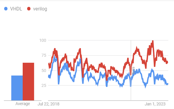
Regarding VHDL simulators, Vivado is considered an averagely famous one from past.

Fantastic article! The information you provide is important. Thank you for sharing!
Thank you for providing me with these article examples. May I ask you a question?
Thank you for writing this post. I like the subject too.
Please tell me more about this. May I ask you a question?
I am now not positive where you are getting your information, but good topic.
I needs to spend a while studying more or working out more.
Thanks for wonderful information I used to be in search of this information for my mission.
Wonderful blog! I found it while surfing around on Yahoo News.
Do you have any suggestions on how to get listed in Yahoo News?
I’ve been trying for a while but I never seem to get there!
Thanks
It’s going to be ending of mine day, except before ending I am reading this impressive paragraph to increase my experience.
Hello, its nice article on the topic of media print, we all understand media is a
impressive source of facts.
Thank you for the good writeup. It in fact
was a amusement account it. Look advanced to far added agreeable from
you! However, how could we communicate?
Wow, this paragraph is fastidious, my younger sister is analyzing these kinds of things, therefore I am going to tell her.
We’re a group of volunteers and starting
a brand new scheme in our community. Your site provided us
with valuable info to work on. You have done an impressive process
and our entire neighborhood can be thankful to you.
Pretty element of content. I just stumbled upon your blog and in accession capital to assert that I get in fact loved account your blog posts.
Any way I will be subscribing in your augment
and even I achievement you access persistently quickly.
Your post challenged my thinking. Thank you!If anyone wants to read the topic in more details then visit 8xbet
Thank you for your help and this post. It’s been great.
F*ckin?tremendous things here. I am very glad to see your article. Thanks a lot and i am looking forward to contact you. Will you please drop me a mail?
Your article helped me a lot, is there any more related content? Thanks!
What a data of un-ambiguity and preserveness of valuable knowledge on the
topic of unpredicted feelings.
Excellent blog here Also your website loads up very fast What web host are you using Can I get your affiliate link to your host I wish my web site loaded up as quickly as yours lol
Your article helped me a lot, is there any more related content? Thanks!