
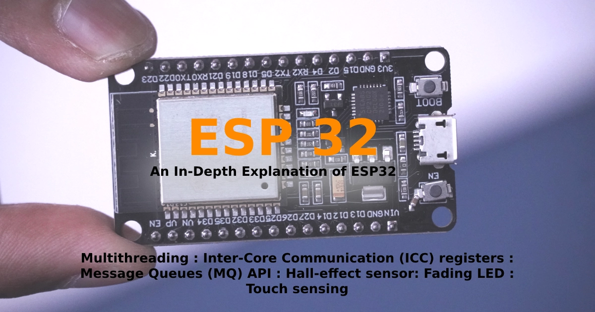
An interesting technological advancement that has completely changed the field of embedded systems is the ESP32 microcontroller. Starting with the fundamentals and working our way up to more complex ideas, we will cover all of the ESP32 features in this tutorial. So buckle up and get ready to discover the wonders of this esp32
This is the content table (click the topic to jump)
topic list:
- What is ESP32?
- Pinout of esp32-wroom-32
- types of boards
- install board manager
- two push buttons
- Bluetooth
- Multithreading
- data exchange between cores
- Hall-effect sensor
- Fading LED
- Touch sensing
What is ESP32?
- Dual-core and 32-bit microcontroller module
- the cores can be controlled individually
- 320 KB of DRAM (Data RAM)
- 200 KB of IRAM (Instruction RAM)
- 4 MB of flash memory
- can be used SD card as an external memory.
- Integrated WIFI, Bluetooth and BLE
- Maximum working clock frequency up to 240 Mz
- Multiple power modes
- Multiple digital and analogue I/O pins
- created and developed by Espressif Systems, a Shanghai-based Chinese company, and is manufactured by TSMC using their 40 nm process
- Released in 2016
- Used in many development boards
- Up to eighteen 12-bit analog to digital converters
- Two 8-bit digitals to analog converters.
- Ten capacitive touch sensors inputs.
- Two I2c bus connections
- Four SPI bus channels
- Two i2s bus connections.
- Three USARTs Serial communications.
- SD card host controller.
- IR remote controller, up to eight channels.
- Motor PWM channels and up to 16 LED PWM channels
- Hall-effect sensor
- Multiple real-time clocked
- Ultra-low power analogue preamp
“Note: some of the functions can’t be used simultaneously “

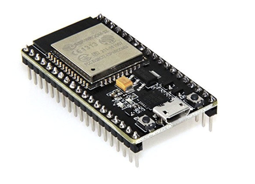
The ESP32 board offers a wide range of varieties
ESP32-WROOM-32 – the most fundamental ESP32 board. It has WiFi, Bluetooth, and a potent processor in addition to all the other features
ESP32-WROOM-32U – has a smaller footprintThe main difference is WROOM-32U don’t have an inbuilt wifi antenna .then you have to connect externally.
ESP32-SOLO-1 – ESP32 with a single core. Although it is less potent than the dual-core variants, it uses less energy
ESP32-WROVER-KIT – a development kit that comes with a breadboard, a power supply, a programmer, and an ESP32-WROOM-32 chip
ESP32-PICO-D4 – a compact, inexpensive board that is made for wearables and Internet of Things (IoT) gadgets
The ESP32-CAM – a development kit that comes with a breadboard, an ESP32-WROOM-32 chip, and a camera module


in this, we focus on ESP32-WROOM-32
Install the board manager
then you have to install the arduino ide board manager this is the link to visit the GitHub page
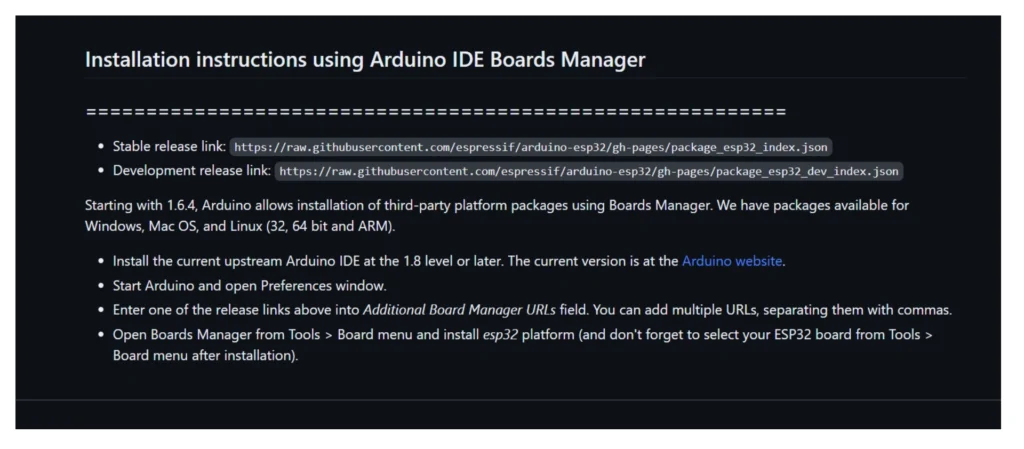
https://raw.githubusercontent.com/espressif/arduino-esp32/gh-pages/package_esp32_index.jsoncopy and paste this link into your arduino IDE
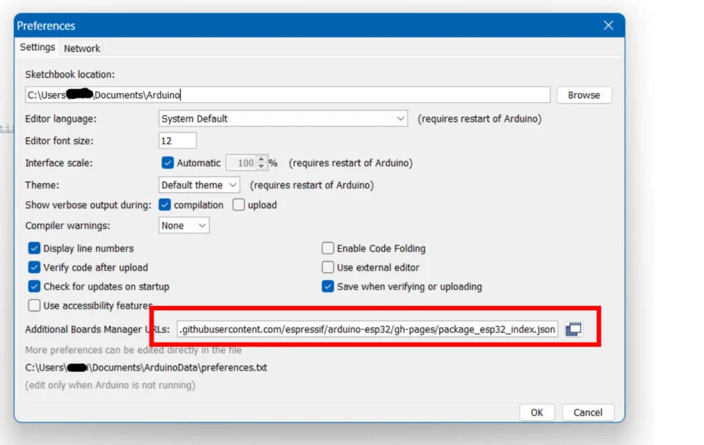
go to ‘file’ and then ‘preferences’

then find this section and paste the above link into this section
then you have to install the boards
to that go to ‘Tool’ then ‘Boards Manager’
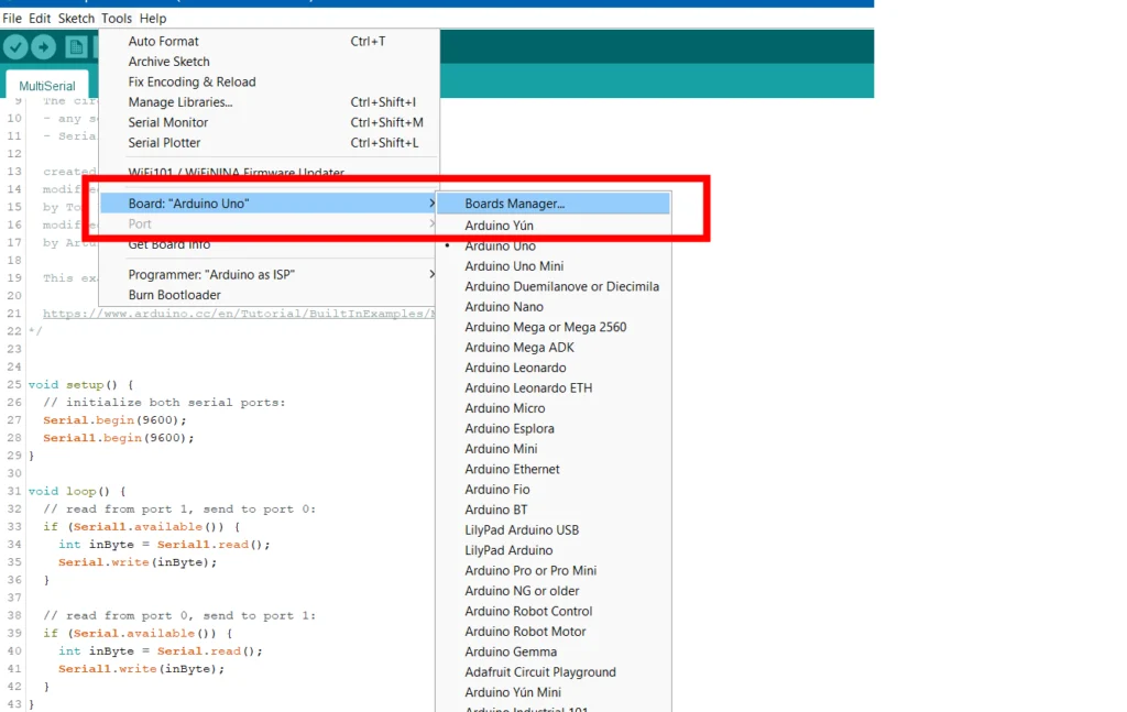
then search ‘esp32 ‘ then install
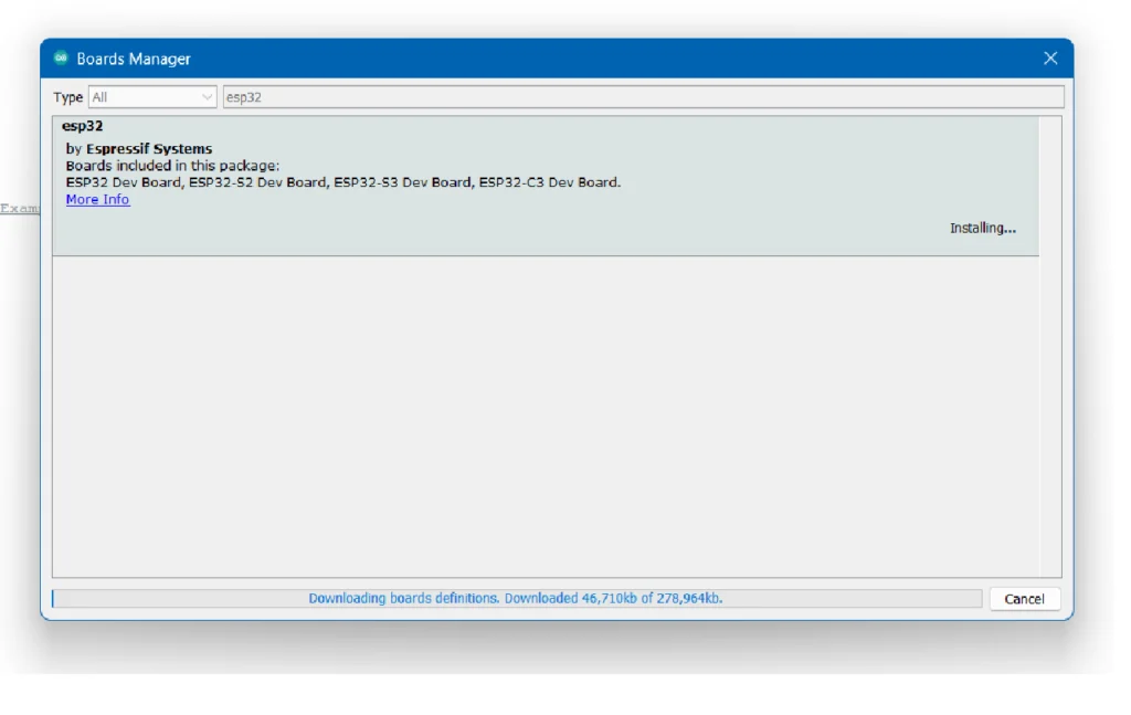
now you can see various types of boards appearing in the list

Then you can send your normal arduino sketchs.
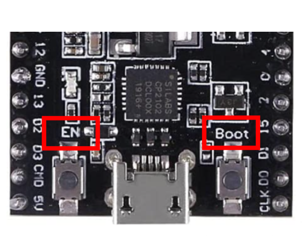
Note: two separate push buttons are included on the board. The first one, referred to as the “EN button,” performs reset-like operations. We press “Boot,” the second button, to upload code to the board. You must click this button in order for the code to be correctly uploaded.
then let’s break down the features of esp32
Bluetooth capability
Bluetooth Classic and Bluetooth Low Energy (BLE) are the two main Bluetooth protocols used for device connectivity. The original Bluetooth protocol, known as Bluetooth Classic, was created for high-bandwidth uses like file transfers and audio streaming then the Bluetooth Low Energy (BLE), on the other hand, is a more modern standard created especially for low-power applications like fitness trackers and smart home gadgets.
Bluetooth Classic
The frequency hopping spread spectrum (FHSS) modulation method is used by Bluetooth Classic. This method spreads the signal over a wide spectrum of frequencies to minimize interference from nearby devices.
Data transfer technique based on packets. Small packets of data are separated and transferred via the Bluetooth connection. Although the length of these packets might vary, they usually measure about 1 kilobyte.
Data speeds of up to 3 Mbps are supported by Bluetooth Classic. This qualifies it for uses that demand a lot of bandwidth, such as audio streaming and file transfers.
range of up to 100 meters
A master-slave architecture underlies Bluetooth Classic’s operation. One device is labelled as the master in this configuration, and another as the slave. By starting the connection and managing the communication, the master device takes the initiative.
4.2 is the Bluetooth classic version
example 01
let’s connect your mobile phone to esp32
this is the sample sketch for the board
#include <BluetoothSerial.h>
//The BluetoothSerial library
//which is included in this line and offers the necessary functions and definitions

BluetoothSerial SerialBT;

void setup() {
  Serial.begin(115200);//A baud rate of 115200 bits per second is selected.
  SerialBT.begin("ESP32 Bluetooth"); // Set the Bluetooth name of ESP32

  Serial.println("ESP32 Bluetooth Serial Monitor");

  if (!SerialBT.begin("ESP32 Bluetooth")) {
    Serial.println("An error occurred initializing Bluetooth");
    while (1);
  }
}

void loop() {
  if (Serial.available()) {
    SerialBT.write(Serial.read());
  }

  if (SerialBT.available()) {
    Serial.write(SerialBT.read());
  }
}
Bluetooth Low Energy (BLE)
Different modulation techniques are used by Bluetooth Low Energy and Bluetooth Classic. Frequency-shift keying, or FSK, is the modulation technique used by BLE. In order to represent the data, this implies that the signal be shifted between two frequencies.
In addition, BLE utilizes a unique packet-based protocol from Bluetooth Classic. In comparison to Bluetooth Classic, BLE packets are significantly smaller. Usually, they are about 20 bytes in size.
the Bluetooth libraries are installed automatically when installing ESP32 libraries
example 02
#include <Arduino.h>
#include <BLEDevice.h>
//The library for Bluetooth Low Energy (BLE) features is included in this line.
#include <BLEServer.h> //This line includes the library for creating a BLE server.

#define SERVICE_UUID "6E400001-B5A3-F391-E000-000000000000"

#define CHARACTERISTIC_UUID "6E400002-B5A3-F391-E000-000000000000"


BLEServer* server;
BLEService* service;
BLECharacteristic* characteristic;

void setup() {
  Serial.begin(115200);

  // Create the BLE server
  server = BLEDevice::createServer();

  // Create the BLE service
  service = server->createService(SERVICE_UUID);

  // Create the BLE characteristic
  characteristic = service->createCharacteristic(CHARACTERISTIC_UUID, BLECharacteristic::PROPERTY_READ | BLECharacteristic::PROPERTY_WRITE);

  // Start the BLE service
  service->start();

  // Start advertising
  server->startAdvertising();

  Serial.println("BLE server started");
}

void loop() {
  // Wait for a BLE client to connect
  BLEDevice* client = server->acceptConnection();

  // If a client is connected
  if (client) {
    // Read the value from the client
    uint8_t value = characteristic->readValue();

    // Print the value to the serial monitor
    Serial.println(value);

    // Write a value to the client
    characteristic->writeValue(value);

    // Close the connection
    client->disconnect();
  }
}
Multithreading
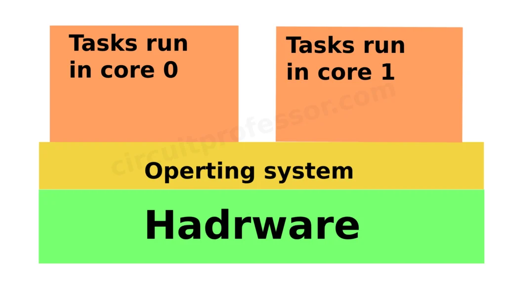
With two cores, the ESP32 is a powerful microcontroller. The performance of your application can be enhanced by allowing you to run multiple tasks simultaneously. because it has 2 cores(dual core)
Running multiple processes simultaneously is known as multithreading. This can be accomplished by splitting the task up into threads, which are smaller units. Independent operation is possible for every thread.
ROTS is an operating system which has been included in more microprocessors.
Here is a list of microcontrollers that have a built-in RTOS:
- ARM Cortex-M series
- AVR series
- PIC series
- ColdFire series
- MSP430 series
- 8051 series
- MIPS series
- HCS12 series
- x86 series
therefore real-time operating system (RTOS) FreeRTOS has been included on the ESP32. The threads are controlled by FreeRTOS, which makes sure they are scheduled to run fairly and effectively.
visit and watch to learn more about RTOS Digi-key
We separate our task list into two cores according to the operating system.
example 03
mainly there are two tasks in this simple project. we have to blink 2 LEDs using two cores.

Arduino sketch
#include <Arduino.h>
#include <freertos/FreeRTOS.h>
#include <freertos/task.h>

// Define the LED pins
#define LED1_PIN 4
#define LED2_PIN 5

// Define the task handles
TaskHandle_t Task1Handle = NULL;
TaskHandle_t Task2Handle = NULL;

// Task 1 function
void Task1(void *parameter) {
  pinMode(LED1_PIN, OUTPUT);

  while (1) {
    digitalWrite(LED1_PIN, HIGH);
    vTaskDelay(500 / portTICK_PERIOD_MS);
    digitalWrite(LED1_PIN, LOW);
    vTaskDelay(500 / portTICK_PERIOD_MS);
  }
}

// Task 2 function
void Task2(void *parameter) {
  pinMode(LED2_PIN, OUTPUT);

  while (1) {
    digitalWrite(LED2_PIN, HIGH);
    vTaskDelay(1000 / portTICK_PERIOD_MS);
    digitalWrite(LED2_PIN, LOW);
    vTaskDelay(1000 / portTICK_PERIOD_MS);
  }
}

void setup() {
  // Create Task 1
  xTaskCreatePinnedToCore(
      Task1,              // Task function
      "Task1",            // Task name
      10000,              // Stack size
      NULL,               // Task parameter
      1,                  // Task priority
      &Task1Handle,       // Task handle
      0                   // Run on core 0
  );

  // Create Task 2
  xTaskCreatePinnedToCore(
      Task2,              // Task function
      "Task2",            // Task name
      10000,              // Stack size
      NULL,               // Task parameter
      1,                  // Task priority
      &Task2Handle,       // Task handle
      1                   // Run on core 1
  );
}

void loop() {
  // Empty loop
}
Online simulate the project (visit to an online simulator)
if you wish to code your own project then you have to understand a few key concepts.
The required libraries for the Arduino framework, FreeRTOS, and the FreeRTOS task management features are included in these lines.
#include <Arduino.h>
#include <freertos/FreeRTOS.h>
#include <freertos/task.h>
These lines specify the pins on the two LEDs the jobs will use to control them.
// Define the LED pins
#define LED1_PIN 4
#define LED2_PIN 5
The task handles for the two tasks are specified in these lines. The task handles can be used to control or see the tasks as well as to keep track of them.
// Define the task handles
TaskHandle_t Task1Handle = NULL;
TaskHandle_t Task2Handle = NULL;
This section outlines Task 1’s purpose. After setting the LED1_PIN as an output pin, the code goes into a loop. In the loop, the LED is first turned on by setting the pin HIGH, followed by a “vTaskDelay” delay of 500 milliseconds, an LED turn off by setting the pin LOW, and another delay of 500 milliseconds. The LED starts to blink as a result of this.
// Task 1 function
void Task1(void *parameter) {
  pinMode(LED1_PIN, OUTPUT);

  while (1) {
    digitalWrite(LED1_PIN, HIGH);
    vTaskDelay(500 / portTICK_PERIOD_MS);
    digitalWrite(LED1_PIN, LOW);
    vTaskDelay(500 / portTICK_PERIOD_MS);
  }
}
This section outlines Task 2’s purpose. Similar to Task 1, but using LED2_PIN and with a new blinking pattern that alternates between 1000ms ON and 1000ms OFF cycles
// Task 2 function
void Task2(void *parameter) {
  pinMode(LED2_PIN, OUTPUT);

  while (1) {
    digitalWrite(LED2_PIN, HIGH);
    vTaskDelay(1000 / portTICK_PERIOD_MS);
    digitalWrite(LED2_PIN, LOW);
    vTaskDelay(1000 / portTICK_PERIOD_MS);
  }
}
A standard Arduino function called once at the beginning of the program is setup().
“xTaskCreatePinnedToCore” is used in this code to create the two tasks.
The task function (Task1 and Task2), task name, stack size, task parameter (in this example, NULL), task priority, task handle (to maintain track of the task), and the core number on which the task should run are all parameters for this function.
Tasks 1 and 2 should run on core numbers 0 and 1, respectively.
void setup() {
  // Create Task 1
  xTaskCreatePinnedToCore(
      Task1,              // Task function
      "Task1",            // Task name
      10000,              // Stack size
      NULL,               // Task parameter
      1,                  // Task priority
      &Task1Handle,       // Task handle
      0                   // Run on core 0
  );

  // Create Task 2
  xTaskCreatePinnedToCore(
      Task2,              // Task function
      "Task2",            // Task name
      10000,              // Stack size
      NULL,               // Task parameter
      1,                  // Task priority
      &Task2Handle,       // Task handle
      1                   // Run on core 1
  );
}
finally, we have the loop()
void loop() {
  // Empty loop
}
Data exchange between cores in ESP32
There are two ways to exchange data between cores in the ESP32
- Using the Inter-Core Communication (ICC) registers
- Using the Message Queues (MQ) API
Using the Inter-Core Communication (ICC) registers
our task is to generate a random number of less than 1000 in one core and then sent that data to the second core.
Then the LED should be blinked and the delay time of the LED is the generated number in the first core. For that, we have to use the ICC register.
#include <Arduino.h>
#include "soc/rtc.h"

// ICC register address for communication
#define ICC_REG_ADDR 0x3ff48000

// Define the LED pin
#define LED_PIN 2

// Task handles
TaskHandle_t Task0Handle = NULL;

// Task 0 function (Core 0)
void Task0(void *parameter) {
  while (1) {
    // Generate random number
    uint32_t randomNum = random(1000);

    // Write random number to ICC register
    WRITE_PERI_REG(ICC_REG_ADDR, randomNum);

    delay(2000);
  }
}

// Task 1 function (Core 1)
void Task1(void *parameter) {
  // Initialize LED pin
  pinMode(LED_PIN, OUTPUT);

  while (1) {
    // Read data from ICC register
    uint32_t delayTime = READ_PERI_REG(ICC_REG_ADDR);

    // Blink LED with delayTime
    digitalWrite(LED_PIN, HIGH);
    delay(delayTime);
    digitalWrite(LED_PIN, LOW);
    delay(delayTime);
  }
}

void setup() {
  // Enable ICC register write access for both cores
  CLEAR_PERI_REG_MASK(RTC_CNTL_ANA_CONF_REG, RTC_CNTL_DIG_PWC_REG);

  // Create Task 0 (Core 0)
  xTaskCreatePinnedToCore(
    Task0,            // Task function
    "Task0",          // Task name
    10000,            // Stack size
    NULL,             // Task parameter
    1,                // Task priority
    &Task0Handle,     // Task handle
    0                 // Run on core 0
  );

  // Create Task 1 (Core 1)
  xTaskCreatePinnedToCore(
    Task1,            // Task function
    "Task1",          // Task name
    10000,            // Stack size
    NULL,             // Task parameter
    1,                // Task priority
    NULL,             // Task handle (not used)
    1                 // Run on core 1
  );
}

void loop() {
  // Empty loop
}
let’s see the key lines above the code
The RTC (Real-Time Clock) module of the ESP32 SDK provides access to the RTC peripheral and related features.
#include "soc/rtc.h"defines the register address for ICC (Inter-Core Communication) used for core-to-core communication.
#define ICC_REG_ADDR 0x3ff48000Generates a random number between 0 and 999 and stores it in the variable
uint32_t randomNum = random(1000);Writes the value of randomNum to the ICC register, allowing communication with Core 1.
WRITE_PERI_REG(ICC_REG_ADDR, randomNum);Enables ICC register write access for both cores by clearing the RTC_CNTL_DIG_PWC_REG mask.
CLEAR_PERI_REG_MASK(RTC_CNTL_ANA_CONF_REG, RTC_CNTL_DIG_PWC_REG);Creates Task0 and assigns it to run
xTaskCreatePinnedToCore(...)Creates Task1 and assigns it to run
xTaskCreatePinnedToCore(...)These are the new important parts of code for communicating with other cores.

Online simulate the project(visit to an online simulator)
Using the Message Queues (MQ) API
A more sophisticated method of data transfer between cores is the MQ API. There are several functionalities offered by the MQ API that are absent from the ICC registers, including:
- a feature that allows messages of any size to be sent and received
- the capacity to communicate with and receive messages from particular cores
- the capacity to prioritize messages sent and received
Create a message queue on each core before using the MQ API. Then, using xQueueSend() and xQueueReceive() routines, you can send and receive messages.
We can duplicate the task that was originally created in (ICC) registers.
#include <Arduino.h>
#include <freertos/FreeRTOS.h>
#include <freertos/task.h>
#include <freertos/queue.h>

// Define the LED pin
#define LED_PIN 2

// Define the message queue size
#define QUEUE_SIZE 10

// Task handles
TaskHandle_t Task0Handle = NULL;
TaskHandle_t Task1Handle = NULL;

// Message queue handle
QueueHandle_t messageQueue;

// Task 0 function (Core 0)
void Task0(void *parameter) {
  while (1) {
    // Generate random delay time
    uint32_t delayTime = random(500, 2000);

    // Send delay time to Task 1 via message queue
    xQueueSend(messageQueue, &delayTime, portMAX_DELAY);

    delay(1000);
  }
}

// Task 1 function (Core 1)
void Task1(void *parameter) {
  // Initialize LED pin
  pinMode(LED_PIN, OUTPUT);

  while (1) {
    // Receive delay time from Task 0 via message queue
    uint32_t delayTime;
    xQueueReceive(messageQueue, &delayTime, portMAX_DELAY);

    // Blink LED with delayTime
    digitalWrite(LED_PIN, HIGH);
    delay(delayTime);
    digitalWrite(LED_PIN, LOW);
    delay(delayTime);
  }
}

void setup() {
  Serial.begin(9600);

  // Create message queue
  messageQueue = xQueueCreate(QUEUE_SIZE, sizeof(uint32_t));

  // Create Task 0 (Core 0)
  xTaskCreatePinnedToCore(
    Task0,            // Task function
    "Task0",          // Task name
    10000,            // Stack size
    NULL,             // Task parameter
    1,                // Task priority
    &Task0Handle,     // Task handle
    0                 // Run on core 0
  );

  // Create Task 1 (Core 1)
  xTaskCreatePinnedToCore(
    Task1,            // Task function
    "Task1",          // Task name
    10000,            // Stack size
    NULL,             // Task parameter
    1,                // Task priority
    &Task1Handle,     // Task handle
    1                 // Run on core 1
  );
}

void loop() {
  // Empty loop
}
let’s see the key lines above the code
This line includes the FreeRTOS library, which is a real-time operating system for microcontrollers.
#include <freertos/FreeRTOS.h>The FreeRTOS task library, which enables task creation and management, is included in this line.
#include <freertos/task.h>The FreeRTOS queue library is included on this line and offers message queues for inter-task communication.
#include <freertos/queue.h>This line defines the size of the message queue as 10.
#define QUEUE_SIZE 10This line defines the message queue handle.
QueueHandle_t messageQueue;With the size and data type that are supplied, the message queue is created by this line.
messageQueue = xQueueCreate(QUEUE_SIZE, sizeof(uint32_t));These are the new important parts of code for communicating with other cores using the Message Queues (MQ) API
Online simulate the project(visit to an online simulator)
Hall-effect sensor
In the esp32, a hall-effect sensor has been included. you can detect the magnetic fields from this.
void setup() {
  // Initialize the serial port
  Serial.begin(115200);
}

void loop() {
  // Read the Hall sensor value
  int value = hallRead();

  // Print the Hall sensor value to the serial port
  Serial.println(value);

  // Wait for 1 second
  delay(1000);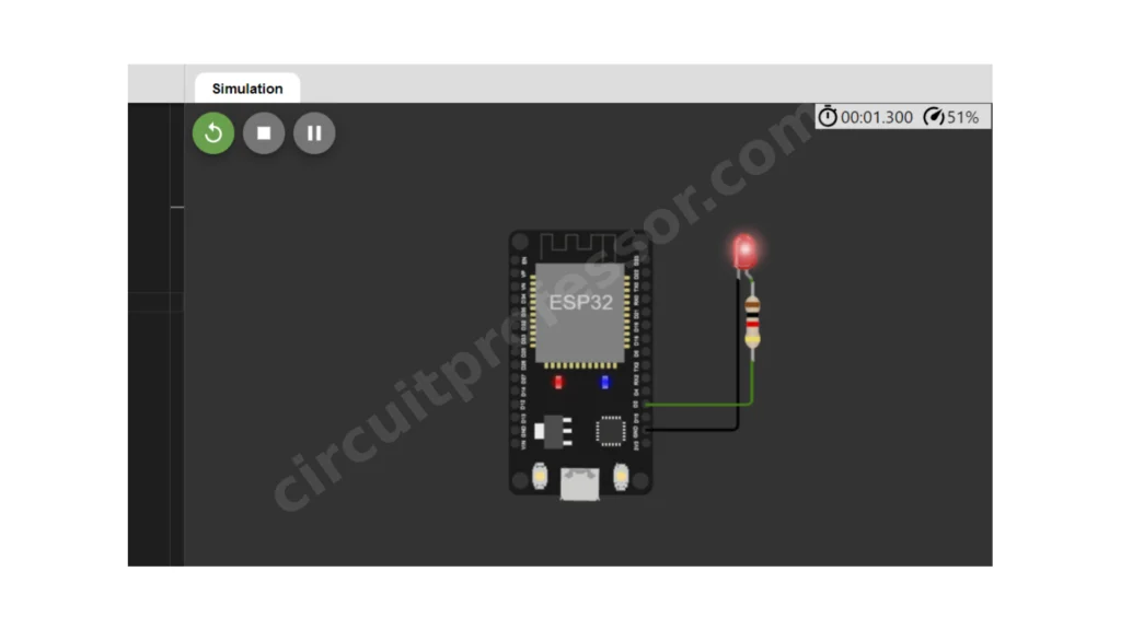
}Fading brightness in LED
Special note: we can’t use analogWrite functions in esp32 boards
// Pin for the LED
const int LED_PIN = 2;

// Fade delay time in milliseconds
const int FADE_DELAY = 10;

// LED brightness
int brightness = 0;

// Fade direction
int fadeDirection = 1;

void setup() {
  // Initialize LED pin as an output
  pinMode(LED_PIN, OUTPUT);

  // Set up PWM on LED pin
  ledcAttachPin(LED_PIN, 0);
  ledcSetup(0, 5000, 8); // Channel 0, 5 kHz frequency, 8-bit resolution
}

void loop() {
  // Fade in and out
  brightness += fadeDirection;

  // Reverse fade direction at limits
  if (brightness <= 0 || brightness >= 255) {
    fadeDirection = -fadeDirection;
  }

  // Set LED brightness using PWM
  ledcWrite(0, brightness);

  // Delay for fade effect
  delay(FADE_DELAY);
}
Touch sensing
there is an additional feature in esp32.that is we can identify the touch sensing using GPIOs
there are 10 capacitive touch-sensing pins
- GPIO4
- GPIO5
- GPIO12
- GPIO13
- GPIO14
- GPIO15
- GPIO26
- GPIO27
- GPIO32
- GPIO33
// Define the touch sensor pins
const int touchPin0 = 4;
const int touchPin1 = 5;

void setup() {
  // Initialize the serial port
  Serial.begin(115200);

  // Set the touch sensor pins as inputs
  pinMode(touchPin0, INPUT);
  pinMode(touchPin1, INPUT);
}

void loop() {
  // Read the touch sensor values
  int touchValue0 = touchRead(touchPin0);
  int touchValue1 = touchRead(touchPin1);

  // Print the touch sensor values to the serial port
  Serial.print("Touch sensor 0: ");
  Serial.println(touchValue0);
  Serial.print("Touch sensor 1: ");
  Serial.println(touchValue1);

  // Wait for 1 second
  delay(1000);
}this is the end of the ESP 32 journey. You have learned key concepts and sensors about the esp32.
Thank you for reading! .this is circuitprofessor.com
Can you be more specific about the content of your article? After reading it, I still have some doubts. Hope you can help me.