A fundamental electrical component that plays a crucial role in the electronic world. Whether it is a simple electronic project or a complex industrial application, resistors are present everywhere which regulates the flow of electric current and ensures the stability and functionality of the circuit. Let’s explore more about resistors.
In this article, we will discuss these topics
- What is a resistor? (click)
- Resistor symbol(click)
- Resistor Classification(click)
- Resistors in Series(click)
- Resistors in Parallel(click)
- Resistor color coding(click)
- How to calculate the resistor value? (click)
What is a resistor?
The resistor can be defined as a passive electrical part with two terminals that are used in electrical circuits to control or limit the flow of electric current which can be used to reduce the current flow and lower the voltage in any particular part of the circuit. It is constructed from copper wires wound around a ceramic rod, and an insulating paint is applied to the resistor’s exterior.
SI unit = ohm
Ohm can be defined as the resistance that develops when a resistor with a one-volt (V) drop across its terminals experiences a current of one ampere (A). The current is proportional to the voltage across the terminal ends. This concept is explained in “Ohm’s Law”.
R= V/I
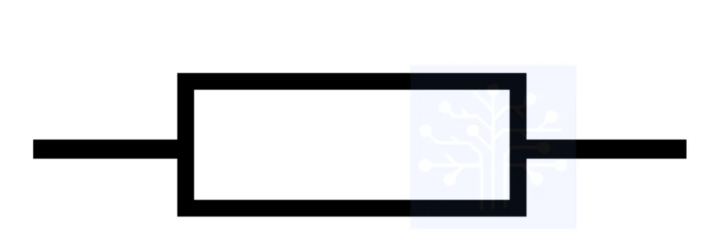
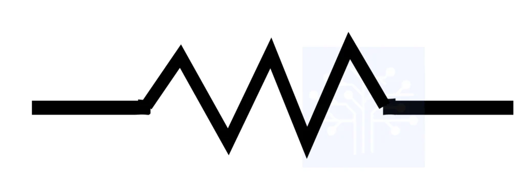
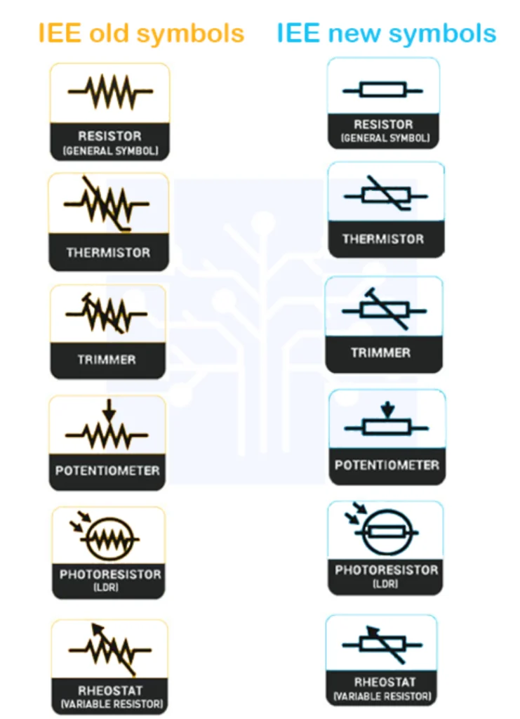
Resistor symbol
IEC fixed resistor symbol
ANSI fixed resistor symbol
Resistor Classification
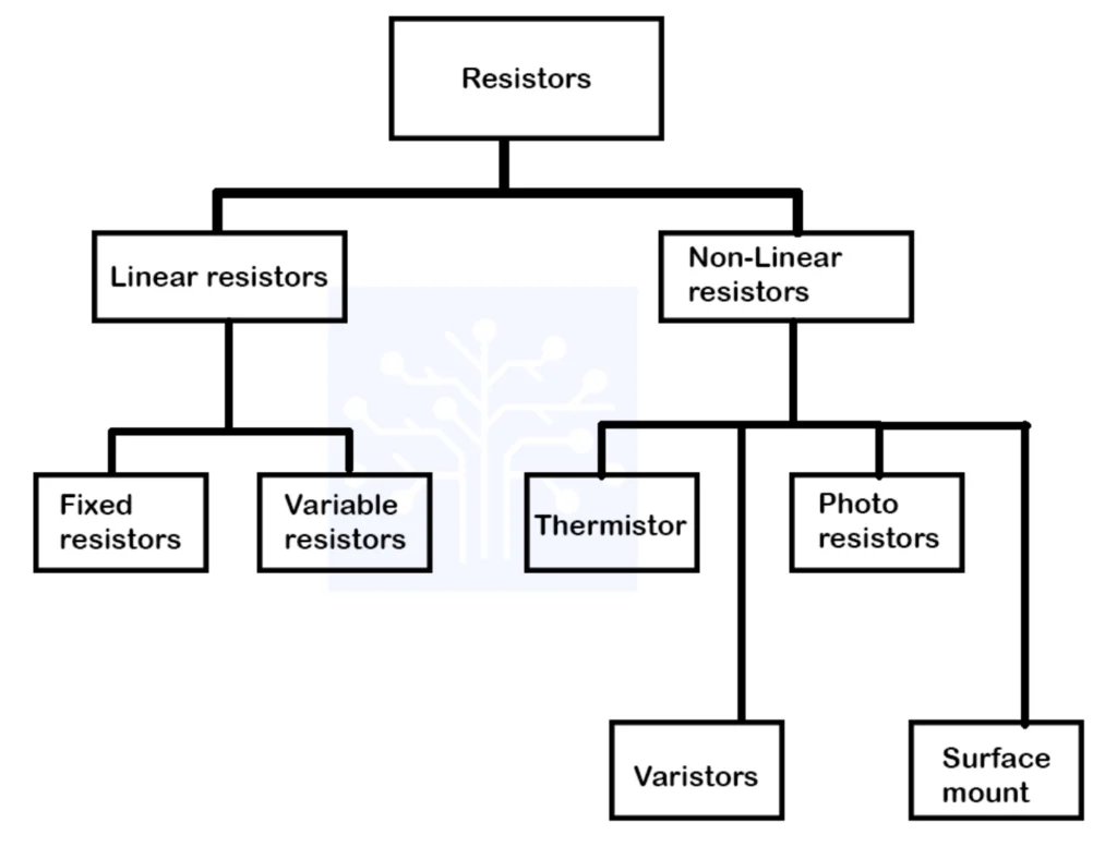
Resistors can be divided into two main groups
- Linear Resistors
- Non-linear Resistors
Linear Resistors
The resistor value changes with a change in applied temperature and voltage which satisfies Ohm’s Law is known as Linear Resistors. The voltage across the resistor is proportional to the current flowing through it.
There are two types of Linear Resistors.
Fixed resistors
Fixed resistors are resistors with specific values that cannot be adjusted or varied by the user. The primary purpose of these resistors is to limit or control the flow of electric current. There are several types of fixed resistors.
Carbon Composition Resistors
The resistance is determined based on the ratio of carbon to the binder.
Applications: They are used in various electronic circuits where precision is not a critical factor.
Film Resistors
The resistance is determined by the length, width, and thickness of the film.
Applications: Commonly used in general electronic circuits.
Metal Film Resistors
When current flows through the resistor, the metal film resists the flow while generating the desired resistance.
Applications: Audio amplifiers, signal processing, and precision measurement equipment.
Metal Oxide Film Resistors
These resistors are similar to metal film resistors, the metal oxide film determines the resistance value.
Applications: Used in precision electronic circuits, medical devices, and instrumentation.
Variable resistors
A variable resistor is a form of resistor in which the user may manually modify the resistance value. In contrast to fixed resistors, Variable resistors allow the resistance to be adjusted within a given range. There are several types of variable resistors.
Potentiometers
A three-terminal resistor with a sliding contact (also known as a wiper). By turning the knob of the potentiometer, the position of the wiper can be changed which alters the resistance between one end of the resistive element and the wiper. The other terminals were connected to the fixed ends of the resistive element.
Applications – volume control, brightness control, and turning the circuit where the user needs to manually adjust a parameter.
Rheostat
A two-terminal where the rheostat’s wiper is connected to one end of the resistive wire. By turning the knob, one can change the resistivity.
Applications – motor speed control and current-limiting device.
Trimmers
Designed for occasional or one-time adjustment rather than continuous or frequent changes. This provides a stable and accurate means of setting specific parameters during the initial setup of devices.
Applications – when precise tuning or calibration is required, such as in oscillators, filters, voltage references
Non-linear Resistors
The resistor value changes with a change in applied temperature and voltage which does not satisfy Ohm’s Law is known as Non-linear Resistor. Its I-V characteristic is not a straight line. There are a few types of Non-linear resistors.
Thermistor
The resistance value changes dramatically with the change in temperature. There are two main types:
- Negative Temperature Coefficient (NTC) Thermistors
- Positive Temperature Coefficient (PTC) Thermistors
Applications – Temperature sensors, and temperature compensation in electronic circuits.
Photo resistor
Photo Resistor or LDR (Light Dependent Resistor) is a light-controlled variable resistor. The photoresistor resistance decreases with an increase in incident light intensity.
Applications – Used in light-sensitive applications, such as automatic streetlights, and photography exposure control.
Varistor Resistor
Resistance decreases significantly when a voltage above a certain threshold is applied.
Applications – Used in surge protection devices, voltage clamping circuits, and power supplies to safeguard electronic components.
Surface Mount Resistor
Resistors designed for surface mount technology (SMT) applications.
Applications – PCB design, Communication Devices, Automotive Electronics.
Various types of resistors are available. Among them, carbon film resistors (carbon resistors) and metal oxide film resistors are mostly used.
carbon film resistors

metal oxide film resistors

Resistors in Series
In a series circuit, the output current of the first resistor flows into the input of the second resistor. Therefore the current is the same in each resistor. The potential drop across the resistors may vary.
Req = R1 + R2 + R3
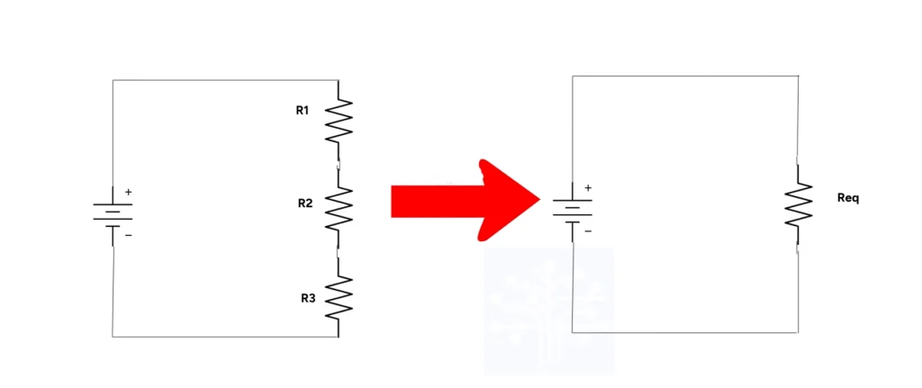
Resistors in Parallel
In a parallel circuit, each resistor has the same potential drop across it, and the current flow through each resistor may be different depending on the resistor. The sum of the individual currents equals the current that flows into the parallel connections.
1/Req = 1/R1 + 1/R2
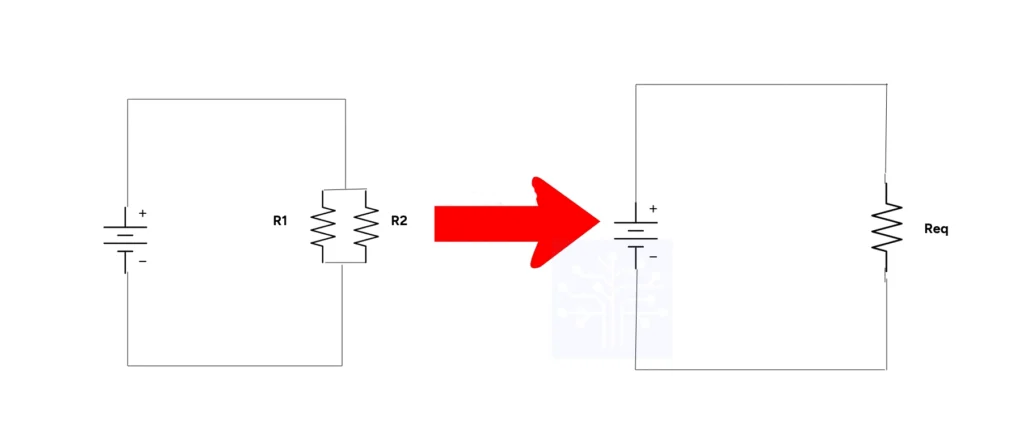
Resistor color coding
Color coding is a technique used to show the temperature coefficient, tolerance, and resistive value of resistors with low wattage ratings because of their small size. Color bands are used on small electronic components because they are inexpensive and can easily printed.
How to read the color codes?
Resistors usually consist of three to six bands which represent resistance, tolerance, and temperature coefficient. These bands are read from left to right.
How to distinguish the reading direction?
The tolerance bandwidth is usually printed with 1.5 – 2 times the width of other bands. A larger gap between the tolerance band and the other bands will be noticeable. The gold or silver band which represents the tolerance must be at the right end since they are never used for significant digits.
It is always better to check the manufacturer’s documentation or use a multimeter to get the exact resistance value.
Tolerance – the percentage of error between the actual measured resistive value and the stated value.
How to calculate the resistor value?
1. Identify the color bands.
Determine the colors of the bands on the resistor. Typically, there are four or five bands. The colors represent digits, multipliers, tolerance, and sometimes temperature coefficients.
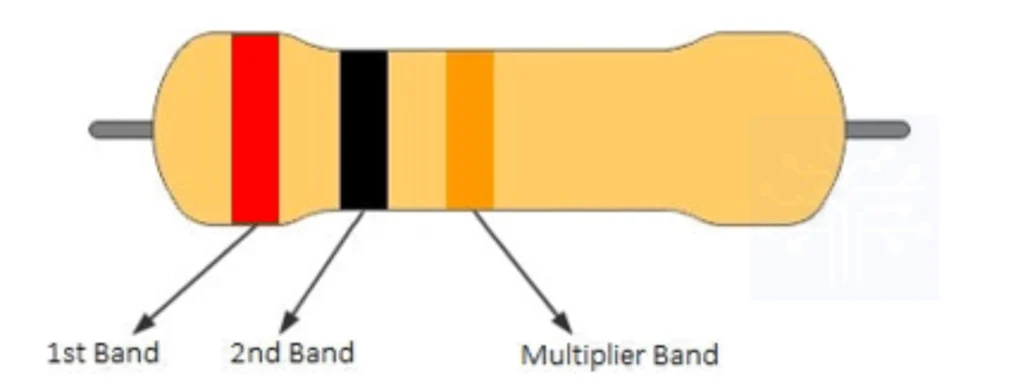
In a three-band resistor, the first two bands represent the first two significant digits, and the third band for the multiplier. Since a tolerance band is not available, the tolerance will always be ±20%.
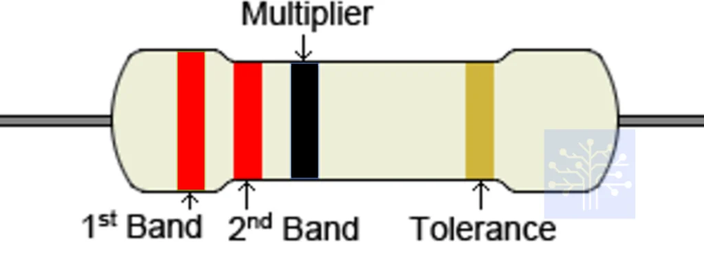
In a four-band resistor, the most common resistor type, the first two bands also represent the first two significant digits and the third band represents the multiplier. The fourth band represents the tolerance.
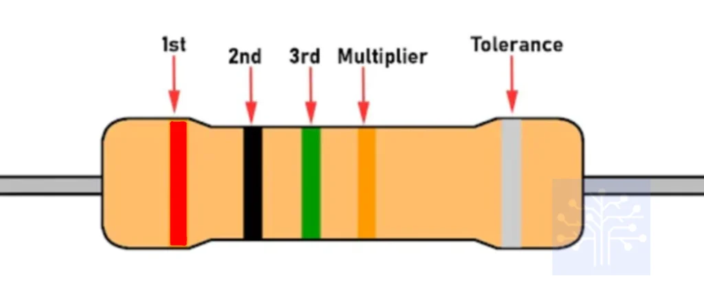
In a five-band resistor, the first three bands represent the first three significant digits and the fourth band represents the multiplier. The fifth band represents the tolerance.
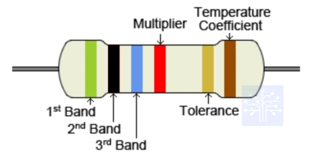
In a six-band resistor, the first three bands represent the first three significant digits and the fourth band represents the multiplier. The fifth band represents the tolerance followed by one extra sixth band which represents the temperature coefficient of resistance (TCR).
2. Read the significant bands.
The first two bands represent significant digits of the resistance value in most of the cases. Use a resistor color code chart to associate each color with a digit. The first band is the tens digit, and the second band is the unit digit.
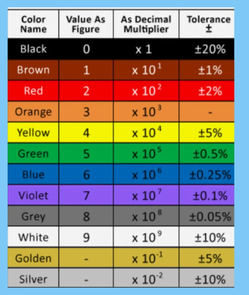
3. Read the multiplier band
The third band represents the multiplier, indicating the power of 10 by which the significant digits are multiplied.
4. Read the tolerance band.
It represents the percentage by which the actual resistance can deviate from the stated value. Common tolerance values are 1%, 5%, and 10%.
5. Calculate the resistance.
Combine the significant and multiplier along with tolerance to calculate the resistance. Example calculation
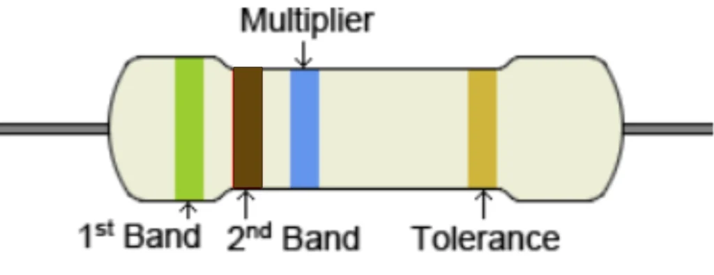
1st band : Green(5)
2nd band: Brown (1)
3rd band: Blue (106)
4th band: Gold(±5%)
The resistance is calculated as follows:
Resistance = (5×10 + 1) × 106 ± 5% = 51 MΩ ±5%


helloI like your writing very so much proportion we keep up a correspondence extra approximately your post on AOL I need an expert in this space to unravel my problem May be that is you Taking a look forward to see you
What i do not realize is in fact how you are no longer actually much more wellfavored than you might be right now Youre very intelligent You recognize thus considerably in relation to this topic made me in my view believe it from numerous numerous angles Its like men and women are not fascinated until it is one thing to do with Lady gaga Your own stuffs excellent All the time handle it up
RIP City
非常に有意義な内容でした。ありがとうございます。
リング 呪いの7日間
素晴らしい情報を共有してくれて、本当にありがとうございます。
Attractive section of content I just stumbled upon your blog and in accession capital to assert that I get actually enjoyed account your blog posts Anyway I will be subscribing to your augment and even I achievement you access consistently fast
Mangaclash Nice post. I learn something totally new and challenging on websites