
A diode serves as a gate to current, functioning as a rectifier. The current flows in only one direction through the diode. The ideal current is reversed to the direction electrons move.
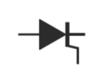
The symbol of the diode
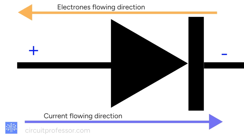
It looks like a gate. If the condition is true, then it opens; otherwise, it does not. The condition is the minimum voltage difference between the nodes of the diode to initiate electron flow. This range is typically from 0.5 V to 0.8 V. The resistance of the diode is in the range of 1000 ohms to 10 ohms.
In this article, we will discuss these topics.
- Inside the diode(click)
- Characteristic of diode(click)
- Current-Voltage Relationship(click)
- Type of diodes(click)
- Application of diodes(click)
- equation of diode(click)
Inside the diode
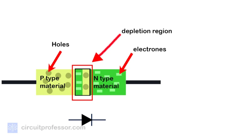
Semiconductors are used in the design of diodes, with silicon and germanium serving as the primary components. In essence, there are two kinds of semiconductors.
Extrinsic semiconductors are compounds in which impurities are added to enhance the concentration of either holes or electrons and intrinsic semiconductors, in which the concentration of electrons and holes is equal at room temperature.
These impurities can be trivalent (boron, indium, aluminum) or pentavalent (such as arsenic, antimony, and phosphorous). The p-type layer is created when trivalent impurities (such as germanium and silicon) are added to a semiconductor. This layer has a positive charge due to the increased number of holes. On the other hand, extra electrons cause a negative charge when pentavalent impurities are added to semiconductors (silicon or germanium), and this layer is known as the n-type layer.
Then, by combining these two layers, we can create a diode. When creating a diode, a depletion layer is automatically generated between these two layers.
When applying external voltage differences, the depletion layer goes to zero. This implies that at a critical point, the layer width goes to zero. In silicon, it is 690mV, and in germanium, it is 300mV.
Characteristic of diode
Mainly, diodes are attached to circuits in forward bias, but Zener diodes use reverse bias.

Reverse-biased
When a voltage source is applied in a reverse-biased diode, its positive side is connected to the diode’s cathode, and its negative side is connected to the anode. The way things are set up, there could be a barrier that prevents current from flowing. In the reverse-biased state, the diode functions essentially as an insulator.
Forward-biased
A forward-biased diode is one in which the cathode is connected to the negative side of the voltage source and the diode’s anode to the positive side. Because it lowers the potential barrier, this design facilitates easy current flow across the diode. The diode conducts electricity when it is forward-biased.
Let’s consider the voltage vs. current graph. In an ideal diode, there is no potential barrier. The graph would then look like this. We consider all bias situations, both forward and reverse when examining the current-voltage relationship.
Current-Voltage Relationship
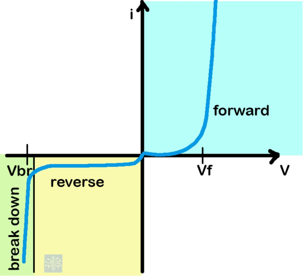
The y-axis represents current, and the x-axis represents voltage. The current changes according to the external voltage difference across the diode. No current flows until the specific voltage(the silicon has a voltage of 690mV, germanium has a voltage of 300mV) difference is reached.
Once this voltage is applied to the diode, current begins to flow through it, and the depletion layer becomes zero. This situation is explained in the forward-bias region of the graph.
When applying voltage in the reverse direction (not the usual way), no current flows through the diode. As the voltage difference increases, at some point, the current starts to flow, and this is the breakdown voltage. The diode is damaged irreversibly at this point. The left-hand side displays this reverse-bias region characteristic.
In germanium, the reverse current is -50 uA, while in silicon, it is -20 uA. Usually, the resistance of the diode is in the range of 1000 ohms to 10 ohms.
Type of diodes
Mainly, there are 10 types of diodes.
Rectifier Diode
commercial product – 1N4007

Its function in electronic circuits is to convert alternating current (AC) to direct current (DC).
High current and voltage handling capacity is a key feature.
Zener Diode
commercial product – 1N4733A

Its purpose is to regulate voltage by keeping a steady voltage across its terminals.
Maintains a steady voltage while operating in the breakdown region.
Light Emitting Diode(LED)
commercial product – LED

Indicator lights are common examples of devices that emit light as electricity flows through them.
Effective transformation of electrical power into light
Schottky Diode
commercial product – BAT54

Faster switching in electronic circuits is made possible by this.
Reduced forward voltage drop in comparison to conventional diodes is a key feature.
Varactor Diode
commercial product – BBY51

There are basically two types of varactor diodes: P-N Junction Varactor Diode and Metal-Semiconductor Varactor Diode (Schottky Varactor Diode).
P-N Junction Varactor Diode
The fluctuation of capacitance in a reverse-biased p-n junction serves as the foundation for this kind of varactor diode. The applied reverse voltage modifies the depletion region width, which in turn modifies the capacitance.
Metal-Semiconductor Varactor Diode (Schottky Varactor Diode)
variable capacitance is achieved by use of a metal-semiconductor junction, which is frequently a Schottky barrier
Both varieties of varactor diodes are helpful in applications like phase-locked loops, voltage-controlled oscillators, and frequency-tuning circuits
SCR (Silicon Controlled Rectifier
commercial product – C106D
The goal is to regulate high-power circuits by letting current flow when a trigger is hit.
Controlled high-power load switching, used for power control applications, is a key feature.
Triac

To provide AC power control, it functions similarly to an SCR but controls both halves of an AC waveform.
The ability to manage AC electricity in both directions is essential for motor speed control and dimmer switches.
Diac

Assists in initiating the TRIAC, guaranteeing symmetric conduction in both AC cycle half-cycles.
Allows bidirectional triggering, which is frequently utilized in AC power regulation using TRIACs.
Tunnel Diode
commercial product – 1N3716

Shows negative resistance; primarily utilized in oscillators with high frequencies.
Special negative resistance quality, perfect for microwave use.
Photo Diode

Its function is to generate current in light-sensitive and light-detection applications.
The ability to convert light energy into electrical current makes it a key feature in optical communication systems and photodetectors.
Application of diodes
Mainly, five key areas are used in diodes.
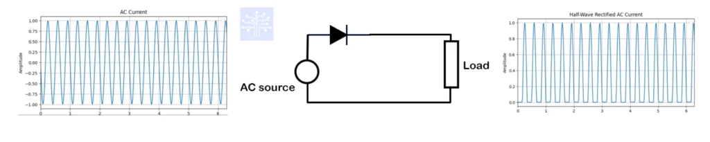
Rectifiers made of diodes
Rectification of current involves creating direct current (DC) from alternating current (AC). There are mainly two ways to rectify the current: half-wave and full-wave. We utilize the property of a diode, where current can flow only in one direction.
Half-wave rectification
In half-wave rectification, only one part of the cycle goes through the diode.
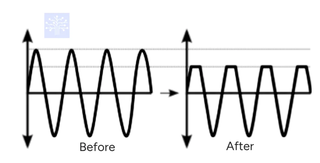
Full-wave rectification
The upper and lower parts of the wave are converted into the same-phase wave in full-wave rectification.

The clipping circuit’s diodes
A device used to “clip” the input voltage in order to keep it from reaching a value greater than a predetermined one is called a clipping circuit or clipper. This device interrupts a cycle’s positive or negative peak value.
There are two general categories of clippers: series and parallel (or shunt). Additionally, three types of clipper circuits can be identified, namely Positive Clipper, Negative Clipper, Biased Positive Clipper, Biased Negative Clipper, and Combination Clipper.
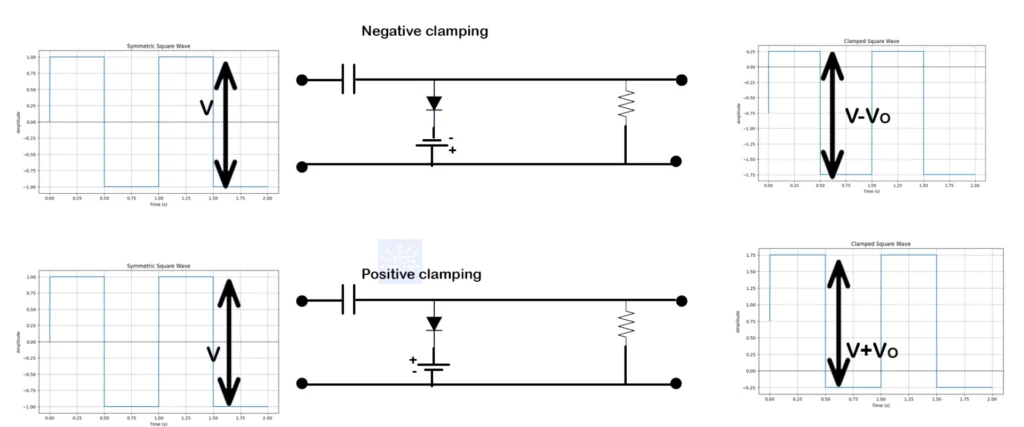
Clamping circuit diodes
Clamper circuits with diodes are used to maintain a specific defined voltage at the peak level in the output voltage. There are two types of clamping: positive clamping and negative clamping. It shifts the entire signal upward or downward until the peak value reaches a specific voltage.
In logical gates, diodes
Diodes are employed in the creation of logic gates, primarily two types: AND gates and OR gates. However, a NOT gate cannot be directly constructed using diodes. To address this limitation, diode-transistor logic (DTL) is employed. Through the application of DTL, it becomes possible to construct NAND and NOR gates.

Reverse current protection diodes
In this context, we focus on the characteristics of unidirectional current flow in diodes. For instance, when a battery pack is connected to a circuit, potential damage may occur if the current flows in the opposite direction. Consequently, to prevent reverse current flow, diodes are positioned in the positive line of the connection. However, this method has two disadvantages.
The diode is required to manage the entire load current, and its forward voltage drop reduces the operational duration of the equipment.

A different approach is to use a parallel (shunt) diode. This strategy allows for a high current flow from the shorted battery while protecting the load. Just like in the earlier technique, the diode must be able to withstand the high current. You can also use a PNP transistor as a high-side switch between the load and the battery as a further precaution for safety.
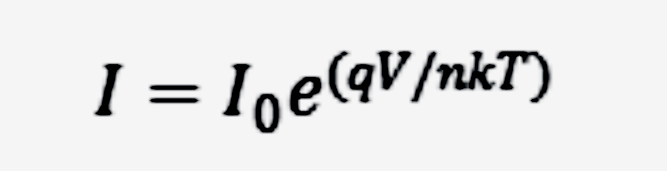
Equation of diode
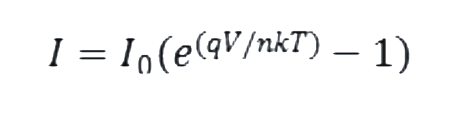
The link between the current passing through the diode and the voltage placed across it is expressed by the diode current equation.
Where?
I is the diode’s current flowing across it.
The diode’s leakage current density when there is no light is shown by the dark saturation current or I_0.
Q is the electron’s charge.
The voltage that is placed across the diode is V.
The ideality factor, denoted as η (eta), represents how close the considered diode behaves to the ideal diode.
And the Boltzmann constant is k.
T is the Kelvin absolute temperature.
Approximately 25.852 mV is the thermal voltage at 300 K (27 °C; 80 °F). It is a known constant at any temperature.
device’s reverse saturation current varies with temperature. In the diode equation, the component involving the exponential term is near to zero when the diode is under reverse bias (not conducting). As a result, the current approaches the value of a very constant reverse current.
The diode conducts when a moderate forward bias voltage is applied, and this causes the exponential term in the equation to grow significantly bigger than 1. This is as a result of the thermal voltage’s relative smallness. Therefore, the forward diode current estimate becomes simpler since we can ignore the “-1” element in the diode equation.
The diode equation is used to figure out and predict how a diode will behave in a circuit. like(Oscillators and Demodulators,Signal Mixing,Clipping and Clamping,Rectification…etc)
Here is the complete explanation of the diode, covering its internal structure, characteristics, types, applications, and the diode equation. Transistors are another fundamental element of electronics.
helloI like your writing very so much proportion we keep up a correspondence extra approximately your post on AOL I need an expert in this space to unravel my problem May be that is you Taking a look forward to see you
Its like you read my mind You appear to know a lot about this like you wrote the book in it or something I think that you could do with some pics to drive the message home a little bit but instead of that this is fantastic blog An excellent read I will certainly be back
Fantastic site A lot of helpful info here Im sending it to some buddies ans additionally sharing in delicious And naturally thanks on your sweat
I have been browsing online more than three hours today yet I never found any interesting article like yours It is pretty worth enough for me In my view if all website owners and bloggers made good content as you did the internet will be a lot more useful than ever before
I was suggested this web site by my cousin Im not sure whether this post is written by him as no one else know such detailed about my trouble You are incredible Thanks
Simply wish to say your article is as amazing The clearness in your post is just nice and i could assume youre an expert on this subject Well with your permission let me to grab your feed to keep updated with forthcoming post Thanks a million and please carry on the gratifying work
I do agree with all the ideas you have introduced on your post They are very convincing and will definitely work Still the posts are very short for newbies May just you please prolong them a little from subsequent time Thank you for the post
Normally I do not read article on blogs however I would like to say that this writeup very forced me to try and do so Your writing style has been amazed me Thanks quite great post
Can you be more specific about the content of your article? After reading it, I still have some doubts. Hope you can help me.
Jinx Manga Very well presented. Every quote was awesome and thanks for sharing the content. Keep sharing and keep motivating others.