

In this article, we focus on C/C++, VHDL, Verilog, Assembly Language, Python, MATLAB, and Simulink, as well as Arduino, RTOS, and Linux. Programming languages used in electronic engineering.

VHDL and Verilog are hardware structural programming languages, while C/C++, Assembly, and RTOS are considered lower-level hardware programming languages. (Unlike VHDL or Verilog, does not involve hardware changes.)
Additionally, Arduino is a relatively simpler hardware programming language, and both Linux and Python have different versions tailored for embedded systems, such as embedded Linux and MicroPython. Linux is used as an operating system, much like Windows.
One advanced programming language is called Python. MATLAB and Simulink are used for analysis and simulation. MATLAB software is required in order to program using MATLAB.
These are the main programming languages, one should learn to become an electronic engineer.
Click to jump
languages
- C/C++ (click)
- VHDL(click)
- Verilog(click)
- Assembly(click)
- Python(click)
- MATLAB and Simulink(click)
- Arduino(click)
- RTOS(click)
- Linux(click)
Comparison
Analysis of the Popularity of Languages in Electronic Engineering(click)

C/C++
C is the first language, while C++ is an advanced language, encompassing several more advanced features compared to C. C++ supports Object-Oriented Programming, the Standard Template Library (STL), Function Overloading, Exception Handling, and Encapsulation.
In practice, C is utilized in many hardware-level programming scenarios, such as with AVR microcontrollers, ARM-based Microcontrollers, ESP8266 and ESP32, PIC Microcontrollers, FPGA boards like Xilinx, 8051 Microcontrollers, and more. When thinking about C++, it’s important to keep in mind that the majority of other devices aside from PIC and 8051 microcontrollers are compatible with C++.
C is the basis for Electronic Engineering in embedded based.
This is basic c code.
#include <stdio.h>

int main() {
    printf("Hello, World!\n");
    return 0;
}
This is Basic C++ code
#include <iostream>

int main() {
    std::cout << "Hello, World!" << std::endl;
    return 0;
}
VHDL
VHDL stands for Very High-Speed Integration Circuit HDL (Hardware Description Language). Mainly, this language is used to program FPGA boards. In ASIC designing, this language is also utilized. There are mainly two types of coding: structural and behavioral. Most electronic engineers utilize a language in the development of custom hardware setups.
Basically, VHDL has 2 sections (Entities, Architectures) read more…
entity
entity entity_name is
  port (
    -- List of input and output ports
    input_port1 : in data_type1;
    output_port1 : out data_type2;
    -- Additional ports if needed
  );
end entity_name;
Architectures
architecture behav1 of AND_ent is
begin
    process(x, y)
    begin
        -- compare to truth table
        if ((x='1') and (y='1')) then  -- Key line: Logical AND operation implementation
	    F <= '1';                 -- Key line: Output 'F' set to '1' when both 'x' and 'y' are '1'
	else
	    F <= '0';                 -- Key line: Output 'F' set to '0' for all other cases
	end if;
    end process;
end behav1;
architecture behav2 of AND_ent is
begin
    F <= x and y;                   -- Key line: Simple assignment using the AND operator
end behav2;Verilog
Verilog is another hardware descriptive language and is more similar to the C language. The purpose is the same as VHDL. Electronic engineers use this language more than VHDL because of 4 reasons.
Simulation Control -Waveforms that are shown depending on the database and may be examined further are a useful tool for readily diagnosing design-related issues. Verilog comes with a built-in simulation control system.
Weak Typing– Verilog has weak typing, which gives it greater data type flexibility. For instance, assigning a signal with the data type reg to another signal with the data type integer won’t lead to a syntax error with the Verilog compiler, unlike in VHDL.
C-like Syntax– Verilog’s syntax is more similar to that of C, making it simpler for people who are already familiar with C or related programming languages to learn and use.
SystemVerilog– A significant extension to Verilog, SystemVerilog is becoming the preferred choice for high-end verification. In instances involving complex system-level verification, this can be helpful.
module multiplexer_2to1 (
  input wire a,
  input wire b,
  input wire select,
  output wire out
);

  assign out = (select) ? b : a;

endmodule
Assembly
The lowest-level hardware programming language is assembly, which is a little more difficult than C. Because it allows for direct CPU control, programs written in assembly could operate more quickly and rapidly. Writing low-level code, such as device drivers, is a suitable fit for assembly
Before writing assembly code, we need to consider the datasheets of the devices. This is because we need to know about memory addresses and other peripherals.
language since it enables direct manipulation of CPU instructions and hardware. Assembly is a good alternative for systems with limited memory since programs written in it usually use less memory than those written in high-level languages.
Assembly languages are sometimes used as bridges to enable the creation of more sophisticated programming languages(High-Frequency Trading (HFT) Platforms, VIC 20 System, Atari ST, and MSX Systems…), which can boost developers’ productivity.
This example assumes that you have a basic understanding of the ATmega328(Arduino uno board IC) architecture and how to set up the necessary registers for serial communication.
.include "m328pdef.inc"

.equ USART_BAUD_RATE = 9600
.equ F_CPU = 16000000

; Initialize USART
USART_Init:
    ldi r16, low(F_CPU / (16 * USART_BAUD_RATE) - 1)
    out UBRR0L, r16
    ldi r16, high(F_CPU / (16 * USART_BAUD_RATE) - 1)
    out UBRR0H, r16
    ldi r16, (1 << RXEN0) | (1 << TXEN0)
    out UCSR0B, r16
    ldi r16, (1 << UCSZ00) | (1 << UCSZ01)
    out UCSR0C, r16

; Transmit a character via USART
USART_Transmit:
    sbis UCSR0A, UDRE0
    rjmp USART_Transmit
    mov r16, 'H'
    out UDR0, r16
    mov r16, 'e'
    out UDR0, r16
    mov r16, 'l'
    out UDR0, r16
    mov r16, 'l'
    out UDR0, r16
    mov r16, 'o'
    out UDR0, r16
    mov r16, ','
    out UDR0, r16
    mov r16, ' '
    out UDR0, r16
    mov r16, 'W'
    out UDR0, r16
    mov r16, 'o'
    out UDR0, r16
    mov r16, 'r'
    out UDR0, r16
    mov r16, 'l'
    out UDR0, r16
    mov r16, 'd'
    out UDR0, r16
    mov r16, '!'
    out UDR0, r16
    ret

; Main program
.org 0x0000
    rjmp main

main:
    call USART_Init
    call USART_Transmit

; End of program
.end
Python
Python is the more usable language in seven cases of electronic engineering.
Design Automation – Python is a powerful tool for automating a wide range of labor-intensive, human-error-prone operations. This covers things like modifying the file extension of Gerber files in order to fabricate PCBs.
example
import os

def modify_gerber_file_extension(directory_path, old_extension, new_extension):
    for filename in os.listdir(directory_path):
        if filename.endswith(old_extension):
            file_path = os.path.join(directory_path, filename)
            new_file_path = os.path.splitext(file_path)[0] + new_extension
            os.rename(file_path, new_file_path)
            print(f"Modified: {filename} -> {os.path.basename(new_file_path)}")

# Example Usage
directory_path = "/path/to/gerber/files"
old_extension = ".gbr"  # Replace with the actual old extension
new_extension = ".gcode"  # Replace with the desired new extension

modify_gerber_file_extension(directory_path, old_extension, new_extension)
Data analysis is a major component of an engineer’s work, and Python is great for it. This covers jobs like data collecting, testing, and automation.
example
# Import necessary libraries
import pandas as pd
import numpy as np
import matplotlib.pyplot as plt

# Simulate data collection and testing
data = {'Engineer': ['Engineer 1', 'Engineer 2', 'Engineer 3'],
        'Test_Result': [85, 92, 78]}

# Create a DataFrame
df = pd.DataFrame(data)

# Print collected data
print("Collected Data:")
print(df)

# Perform data analysis (e.g., calculate average)
average_result = np.mean(df['Test_Result'])
print("\nAverage Test Result:", average_result)

# Plot the data
df.plot(x='Engineer', y='Test_Result', kind='bar', legend=False)
plt.title('Test Results of Engineers')
plt.ylabel('Test Result')
plt.show()

# Automate data analysis tasks
# (In a real-world scenario, this might involve more complex automation processes)
print("\nAutomation: Data analysis tasks automated successfully.")
Simulation – Circuits can be simulated with Python. PySpice, for instance, offers an interface for circuit simulators such as Xyce or Ngspice.
example
from PySpice.Spice.Netlist import Circuit
from PySpice.Unit import ohm, uF, V, mA, Hz

# Define the circuit
circuit = Circuit('Simple RC Circuit')

# Add components to the circuit
circuit.V('input', 1, circuit.gnd, V(value=5, dc_offset=0, frequency=1@Hz))
circuit.R(1, 1, 2, 1@ohm)
circuit.C(1, 2, circuit.gnd, 1@uF)

# Simulation settings
simulation = circuit.simulator(temperature=25, nominal_temperature=25)
analysis = simulation.transient(step_time=1@uF, end_time=10@uF)

# Print simulation results
for time, voltage in zip(analysis.time, analysis['input']):
    print(f'Time: {time}s, Voltage: {voltage}V')
Making Schematics – Schematics can be made with Python. For instance, you can use Python objects in SKiDL to describe schematics as a netlist file.
example
from skidl import *

# Create electronic components using SKiDL
resistor = Part("Device", "R", value="1k")
capacitor = Part("Device", "C", value="1uF")
led = Part("Device", "LED")
voltage_source = Part("Source", "V", value="5V")

# Connect components to form a simple circuit
net_1 = Net("N1")
net_2 = Net("N2")

resistor[1,2] += net_1
capacitor[1,2] += net_1, net_2
led[1,2] += net_2
voltage_source[1,2] += net_1

# Generate the netlist and save it to a file
generate_netlist(file="simple_circuit.net")

print("Schematic created and netlist generated successfully.")
Python is capable of automating file processing operations, which are frequently necessary in many process workflows.
Unit Handling – When performing engineering math, Python modules such as Pint make it easier to handle physical numbers.
example
# Import the Pint module
from pint import UnitRegistry

# Create a Pint UnitRegistry
ureg = UnitRegistry()

# Define physical quantities with units
length = 5.0 * ureg.meter
width = 2.0 * ureg.meter

# Calculate the area
area = length * width

# Display the result
print(f"The area is: {area.to(ureg.square_meter)}")
Hardware Description Languages (HDLs) – For tasks like testing, data collecting, and automation, Python can be used in conjunction with HDLs like Verilog and VHDL.
example
# Python script for testing HDL modules

import subprocess

def simulate_verilog():
    # Simulate Verilog module using a simulator like ModelSim
    subprocess.run(["vsim", "-do", "simulate_verilog.do"])

def simulate_vhdl():
    # Simulate VHDL module using a simulator like ModelSim
    subprocess.run(["vsim", "-do", "simulate_vhdl.do"])

def collect_data():
    # Python code for data collection or analysis
    print("Collecting and analyzing data...")

def main():
    print("Testing and Automating with Hardware Description Languages (HDLs)")

    # Simulate Verilog module
    simulate_verilog()

    # Simulate VHDL module
    simulate_vhdl()

    # Collect and analyze data
    collect_data()

if __name__ == "__main__":
    main()
MATLAB and Simulink
MATLAB and Simulink are widely used in electronic engineering for 8 uses.
Signal and Image Processing – Signal and image processing systems are designed and simulated by engineers using MATLAB and Simulink. To create real-time signal processing systems, they are able to investigate methods, analyze signals, and weigh implementation trade-offs.
Control Systems – Digital control systems for motors, power converters, and battery systems are developed using MATLAB and Simulink.
Embedded Systems -They speed up the process of designing embedded systems with interacting parts.
Technical or Math Computation – A variety of tools for technical and mathematical computing are available in the MATLAB toolbox. These techniques can be applied to data analysis, visualization, matrix manipulation, mathematical computation, and algorithm building.
AI for Electrification – Using MATLAB and Simulink, you may create AI-based reduced order models (ROMs) to simulate more quickly and represent complex electrical component behaviors. AI-based virtual sensors and control schemes for motors, batteries, power converters, energy management systems, electric cars, and grid systems can be developed, trained, and tested.
DSP System Design – MATLAB tools are needed in the DSP system to process images and data. You require MATLAB for data import, analysis, augmentation, and application development.
Control System Design – Automatic control systems are designed using the control system toolbox. We are able to monitor the model, examine the algorithm, and manage the simulation in this design system.
Test and Measurement – MATLAB Simulink technologies are useful in the test and measurement portion of electronic engineering for exchanging data and gathering information from external hardware.
% MATLAB script for printing "Hello, World!"

disp('Hello, World!');
Arduino
Arduino is a widely renowned open-source platform for programming devices and creating embedded systems. It serves as an excellent platform for aspiring electronic engineers, commonly employed as a prototyping tool in various scenarios. The language employed is a combination of C and C++.
void setup() {
  // Initialize serial communication
  Serial.begin(9600);
}

void loop() {
  // Print "Hello, World!" to the Serial Monitor
  Serial.println("Hello, World!");

  // Wait for a moment
  delay(1000);
}
RTOS
RTOS stands for a real-time operating system. It involves advanced C code with specific libraries. RTOS is utilized in high-speed real-time processes and parallel processing. For example, when using the ESP32, which has two cores, RTOS allows you to write tasks focusing on a specific core. Basically, we have 36 types of RTOS (Zephyr, NuttX, Keil RTX, FreeRTOS, etc.), meaning the libraries and specific functions are included for particular applications. The famous one is FreeRTOS.
The main 6 advantages of using RTOS
Managing Hardware Resources – RTOS is designed to efficiently oversee hardware resources in embedded systems. This is achieved by creating multiple threads of software execution and utilizing a scheduler to manage these threads.
Handling Complex Applications – RTOS introduces a new abstraction level that simplifies the execution of more complex applications. Its compact size makes it suitable for microcontrollers (MCUs).
Dealing with Interrupt Sources and Communication Interfaces – RTOS is commonly used in scenarios with numerous interrupt sources, functions, and communication interfaces. The decision to use an RTOS is often influenced by the complexity of the application tailored for MCUs.
Working with Networking Stacks, GUIs, and File Systems – The need for an RTOS becomes evident when dealing with design requirements such as TCP/IP or other complex networking stacks, intricate GUIs, or file systems.
Creating a Multi-tasking and Deterministic Run-time Environment – RTOS facilitates the suspension of tasks while prioritizing those with real-time requirements. The RTOS software provides mechanisms for inter-thread synchronization and software timer services.
Used in Environments with a Large Number of Events – RTOS finds application in environments with a substantial number of events that require quick processing or adherence to specific deadlines. Examples include industrial control, telephone switching equipment, flight control, and real-time simulations.
This is a multithreading code for esp32
#include <Arduino.h>
#include <freertos/FreeRTOS.h>
#include <freertos/task.h>
// Task handlers/////////////////////////////////////////////////////////
TaskHandle_t task1Handle;
TaskHandle_t task2Handle;
/////////////////////////////////////////////////////////////////////////
// Task function for Task 1
void task1(void *parameter) {
while (true) {
int randomNumber = random(100);
Serial.print("Random number in Task 1: ");
Serial.println(randomNumber);
delay(1000);
}
}
// Task function for Task 2
void task2(void *parameter) {
while (true) {
Serial.println("circuitprofessor.com");
delay(2000);
}
}
//////////////////////////////////////////////////////////////////////
void setup() {
Serial.begin(115200);
// Create Task 1 with task handler
xTaskCreate(task1, "Task 1", 10000, NULL, 0, &task1Handle);
// Create Task 2 with task handler
xTaskCreate(task2, "Task 2", 10000, NULL, 1, &task2Handle);
}
////////////////////////////////////////////////////////////////////
void loop() {
// Empty loop
}Linux
We are familiar with Linux as an operating system, similar to Microsoft or macOS for PCs. However, Linux is extensively utilized in many electronic-based systems, such as smart TVs like LG that use webOS, as well as devices like iPods, PlayStations, and Xbox. Additionally, numerous robotics platforms leverage this operating system like ROS.
Bash is the primary language for Linux systems, encompassing these fundamental 15 commands widely utilized in Linux-based environments.
ls: List files and directories in the current directory.cd: Change the current directory.pwd: Print the current working directory.mkdir: Create a new directory.cp: Copy files or directories.mv: Move or rename files or directories.rm: Remove files or directories.cat: Display the contents of a file.nanoorvi: Text editors for creating or modifying files- .
echo: Print text or variables to the terminal. man: Display the manual or help pages for a command.chmod: Change the permissions of a file or directory.chown: Change the owner of a file or directory.ps: Display information about active processes.kill: Terminate a process.
Embedded systems operate using Linux in various fields such as factory automation, electronics, and medical devices. That’s why, as electronic engineers, we should learn Linux.
these are 8 use cases of Linux
Prototyping -Linux is frequently employed as a development environment for prototyping electronic designs like prototype circuit boards for a new sensor.
Embedded Systems – Linux finds common usage in embedded systems, which are computer systems dedicated to specific functions within larger mechanical or electrical systems like larger home automation systems.
Device Drivers – Linux is employed for writing device drivers, programs that control specific devices attached to a computer.
Real-Time Systems – Linux can be applied in real-time systems, which necessitates high consistency in response times.
Process Scheduling – Linux is used to manage various services, including process scheduling.
Application Scheduling – Linux also handles application scheduling.
Managing Hardware Resources – Linux-based operating systems utilize the Linux kernel to manage device hardware resources.
Software Packages – Linux is utilized for managing software packages that power the remainder of the operating system.
under Linux systems, you can use any language like c,c++, Arduino, python…etc.
here is how the run simple c code.
#include <stdio.h>

int main() {
    printf("Hello, World!\n");
    return 0;
}
Afterward, your file should be compiled and executed using Bash:
gcc hello.c -o hello   # Compile the file

./hello # Execute the filePopularity of Languages in Electronic Engineering

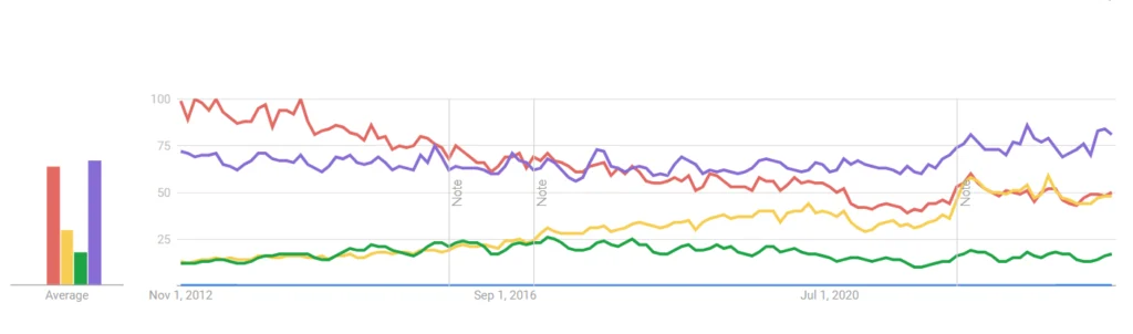
Languages such as RTOS, MATLAB, Assembly, VHDL, and Verilog have significantly fewer users compared to Python, Linux, C, and Arduino. That implies it would be more helpful for you to learn these 4 main languages to become an electronic engineer.
I loved as much as you will receive carried out right here The sketch is attractive your authored material stylish nonetheless you command get got an impatience over that you wish be delivering the following unwell unquestionably come more formerly again since exactly the same nearly a lot often inside case you shield this hike
This asset is remarkable. The wonderful substance shows the designer’s enthusiasm. I’m astounded and envision more such fabulous material.
Your blog is a true hidden gem on the internet. Your thoughtful analysis and engaging writing style set you apart from the crowd. Keep up the excellent work!
I’d like to find out more? I’d love to find out more details.
Great post. I was checking constantly this weblog and I’m inspired! Very helpful information specifically the closing phase 🙂 I care for such info much. I was seeking this particular information for a very lengthy time. Thank you and good luck.
Thank you for your help and this post. It’s been great.