

LDI, ADD, LDS, STS, IN, LDS, OUT, MOV, INC, SUB, COM, JMP,.EQU.ORG, BRNE, CALL, RET and RCALL are the basic assembly command.
we cover all commands using simple codes .and Atmel studio is the best programming simulation software and IDE for doing hardware programming.

if you want to know about the internal architecture of the microcontroller visit this.
software installation
Atmel studio is the old name and microchip studio is the modern software.

- After software installation, you have to set up your software to programme
- this is the first interface
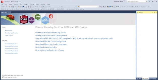
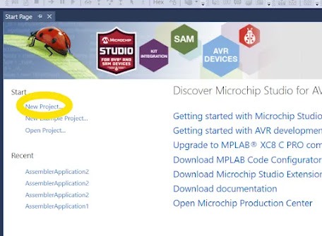
- then you have to click “New project”
- this is your pop-up window and then select Assembler
.webp)
- then select the AVR Assembler project (double click)
.webp)
- your popup window luck like this
.webp)
- then search ATmega328p / click ok
.webp)
- this is your final programming window.
.png)
- well done! now you can start coding
Subtopics
LDI
copies 8bit data into the general purpose registers
LDI Rd,k; load Rd (d is the destination of general-purpose register) with immediate value k (k will be any value )
(“; ” after using a semicolon, we can type a comment on the programme)
“LDI instruction can be only used between 16 and 31 GPR”
Ex:
LDI R21,0x27 ;load R20 register to 0x25 (0x25 is hexadecimal value)
LDI R24,0x24;
LDI R31,0x14;
LDI R16,0xff ; (we cannot use R0-R15 registers)
ADD
ADD is simply the addition of two numbers then store in the first value’s location
ADD Rd, Rk; ADD Rk to Rd and store in Rd location
Ex:
LDI R23,0x25 ;
LDI R16,0x24;
ADD R16,R23 ; R23(value = 0x25) is added to R16(value = 24) and then  store in R16's location
LDI R25,0x568 ;
LDI R19,0x325;
ADD R25,R19 ;
LDS
LDS is the value load direct from data space
LDS Rd,k
we can load any value which in any location (simply say space)of the data memory to 0 to 31 registers (General purpose registers)( 0<= d =<31). usual microcontroller space (data memory ) can be extended $00000 to$FFFF. the k value should be any address value from space (recall – $0000 to $ffff)
Ex:
LDS R0,0x250 ; R0 value is same as location 0x250LDS
R16,0x450 ; R16 value is same as location 0x450
LDS R31,0x220 ; R0 value is same as location 0x220
” LDI’s working range between R16-R31 but LDS has R0-R31″
STS
STS instruction is storing data directly in data space
STS K,Rr ; simply STS mean storing Rr value in location k (k can be any location between $0000- $FFFF).first, we can define any value to the register and then copy that value to any other location using STS instruction.
Ex:
LDI R17,0x34 ;
STS 0x32 ,R17; the value of R17 is copied to the 0x32 location
STS 0x36,R17; the value of R17 is copied to the 0x36 location
STS 0x55,R17; the value of R17 is copied to the 0x55 location
“In STS instructin ,we can’t assign value into SRAM.first we need to assign value to Genaral pupuse registers (R0-R31).then we can copy that value to the SRAM using STS.”
IN
IN instruction is load values from i/o locations to general purpose registers.
IN Rd,A ; load the value from I/O registers .(I/O registers are 0-63 registers ).
starting location should be 0-31 (0<=d<=31)and the values should be taken from 0-63(0=<A=<63) addresses.
this is mostly the same as LDS but LDS has the accessibility of all addresses in data memory but IN instruction can only load the first 63 values as A.
but LDS instruction has not included some AVRs.but IN instruction is available in all AVRs.
the LDS instruction has 2 machine cycles. 4-byte instruction memory. but IN only has one machine cycle and 2 -byte instruction memory.
Ex:
LDI R16,0x99;
IN R2,0x16;
” We can use port names in IN instruction”
IN R3,PINBwhat are the port and pin
OUT
OUT instruction is storing the output in the I/O location
OUT A, Rd
; store (sending) output value to the I/O location (0<=A<=63),and the value
should be stored in General purpose registers ( 0<=d=<31).
Ex:
IN R17,PINB ;take input from PINB to R17
OUT PORTC,R17 ;  R17 stored value output to PORTBC
.DEVICE atmEGA32
.ORG 00
AGAIN IN R16, PINB; bring input from PINB to R16
      OUT PORTC,R16;output to  PORTC that value
      JMP AGAIN; jump to again previous position
MOV
MOV is an instruction which can copy data among the GPR registers (R0-R31)
MOV Rd, Rr; Rd=Rr (copy Rr value to Rd register)
Ex:
MOV R10,R16;R10=R16INC
INC simply increase the value of the register
INC Rd; Rd=Rd+1
Ex:
LDS R23,0x233 ; load value R23 register from 0x233
INC R23 ; increase value of R23 value by 1
STS 0x250,R23;store R23 value in 0x250 location
SUB
SUB is the subtraction of the two numbers.
SUB Rr, Rd = Rr-Rd; after subtraction, the value is stored in Rr location
Ex:
LDS  R23,0x234 ;load value from 0x234 location
LDI R16,0x20 ; define value to R16 and which is 0x20
SUB R16,R23 ;  R16=R16-R23
STS 0x350,R16 ; store value of R16 in 0x350
COM
COM is the complement of the value
COM Rd; complement of Rd
Ex:
LDI R16,0x20 ; define value to R16 and which is 0x20
COM R16;after taking complement the value is stored in the same location
STS 0x350,R16 ; store value of R16 in 0x350
.EQU
.EQU(equate) is defining a constant value or a fixed address
Ex:
.EQU MYCOUNT = 0x95 ; define a constant
.EQU MYREG = 0x23 ; assign memory location to MYREG
.ORG
.ORG(origin) is indicated at the beginning of the programme from the first address value
.INCLUDE
.INCLUDE is a directive which tells to AVR assembler to add constants of files to our programme.
this is like including a library in other languages.
Ex:
.INCLUDE "M32DEF.INC" ;include for ATmega32.BRNE
.BRNE is status-checking instructions and then the programme counter moves to the previous location.
first, you have know about SREG register. the zero flag (z) is used to continue this process.
Let’s clear this BRNE instruction from the example
Ex:
.INCLUDE "M32DEF.INC"
.DEVICE ATmega32
.ORG 0x0000
LDI R16,69 ;
LDI R17,0;
LDI R18,2;
LOOP1:ADD R17,R18;    create loop and we need add R17 toR18 everytime
             DEC R16;    decrease the R16 value by 1
             BRNE LOOP1;  check whether the R16 IS ZERO or not , if it is not jump              to loop1 location .and this     loop is continued until the R16 = 0. if the R16 is zero then the programme counter jump out from loop
OUT PORTC, R17; the final value of after addition send to portc
CALL/RET
CALL point to some locations for the programme counter and then the programme counter jumps to that location. after doing that process, the programme counter goes back to the previous jumped location. RET (return) instruction is used to go back jumped location.
programme counter should come back to the previous location after the jump occurs .then we have to store the present address before the jump. therefore we should define that location at the beginning of the programme.
Ex:
.INCLUDE "M32DEF.INC"
.DEVICE ATmega32
.ORG 0x0000
      LDI R16,HIGH(RAMEND);
RAMEND is finding end of the ram location and HIGH is                                         the upper address of the last ram address. that location is assigned to R16.
      OUT SPH,R16;
send that value to the SPH   location
      LDI R16,LOW(RAMEND);
the LOWER address of the last ram address. that location is assigned to R16.
      OUT SPL,R16;
send that value to the SPL location
BACK :
      LDI R16,0x56 ;load 0x56 value to R16
      OUT PORTB,R16 ;VALUE OF R16 is sent to PORTB
      CALL DELAY ;DELAY fucntion is called then jump to DELAY function
      LDI R16,0x34;load 0x34 value to R16
      OUT PORTB,R16;stored R16 value send to PORTB
      CALL DEALY;time delay
      RJUMP BACK;keep doing this process infinitely
;----------------------------this is the delay subroutine
      .ORG 0x400; time delay function starting address
DELAY:
       LDI R34,0xFF;
AGAIN:
       NOP; NOP is no operation ,which means a clock cycle is wast.that time also include to delay fucntion
       NOP
       DEC R34
       BRNE AGAIN ;jump to previous again location and repeat the process
       RET; return to caller
SBI
SBI is set bit in I/O register
Ex:
SBI PORTB,2;There are 8 bits in PORTB and SBI set 1 (high) in 2 bit in PORTBCBI
CBI is CLEAR bit in I/O register
Ex:
CBI PORTB,3;3rd bit is cleared in PORTBSBIC
SBIC is skipping to the next instruction if a bit is low (0) in the I/O register
Ex:
SBIC PORTB,4; check the 4th bit and if the bit value is low (0) then the next instruction is skippedSBIS
SBIS is skipping to the next instruction if a bit is high (1) in the I/O register
Ex:
SBIS PORTB,7;check the 7 the bit and if the bit value is high (1) then the next instruction is skippedThis is the fundamentals of ASSEMBLY instruction. If you found this post interesting, leave a comment below.
microprocessors-https://circuitprofessor.com/microprocessors-and-computer-interfacing/
bose is always overrated by these people…Bose sucks stop hyping bose
This blog was… how do you say it? Relevant!! Finally I
have found something which helped me. Thank you!
Thank you for your sharing. I am worried that I lack creative ideas. It is your article that makes me full of hope. Thank you. But, I have a question, can you help me?
Your point of view caught my eye and was very interesting. Thanks. I have a question for you.